
Methods and system for operating a variable voltage controller

a variable voltage controller and variable voltage technology, applied in the direction of engine-driven generators, circuit arrangements, transportation and packaging, etc., can solve the problems of less efficient electric power use of electric machines, and achieve the effects of improving the efficiency of electric machines, improving the efficiency of battery charging, and improving electrical system efficiency

Active Publication Date: 2019-04-18
FORD GLOBAL TECH LLC
View PDF5 Cites 3 Cited by
  • Summary
  • Abstract
  • Description
  • Claims
  • Application Information

AI Technical Summary

Benefits of technology

This patent describes a method for improving the efficiency of an electric system, especially the efficiency of an electric machine, by controlling the voltage of the battery. By using a transistor to control the voltage of the battery, the method can adjust the voltage to match the battery voltage, which can improve battery charging efficiency. This approach can be used in either a buck mode or a boost mode, and can reduce over boosting when the battery charge is low and increase the battery voltage boost capability.

Problems solved by technology

However, if the voltage output from the battery and the inductor is above or below a desired voltage where the electric machine operates efficiently, electrical power use by the electric machine may be less efficient than is desired.

Method used


Image

  • Methods and system for operating a variable voltage controller
  • Methods and system for operating a variable voltage controller
  • Methods and system for operating a variable voltage controller

Examples


Embodiment Construction

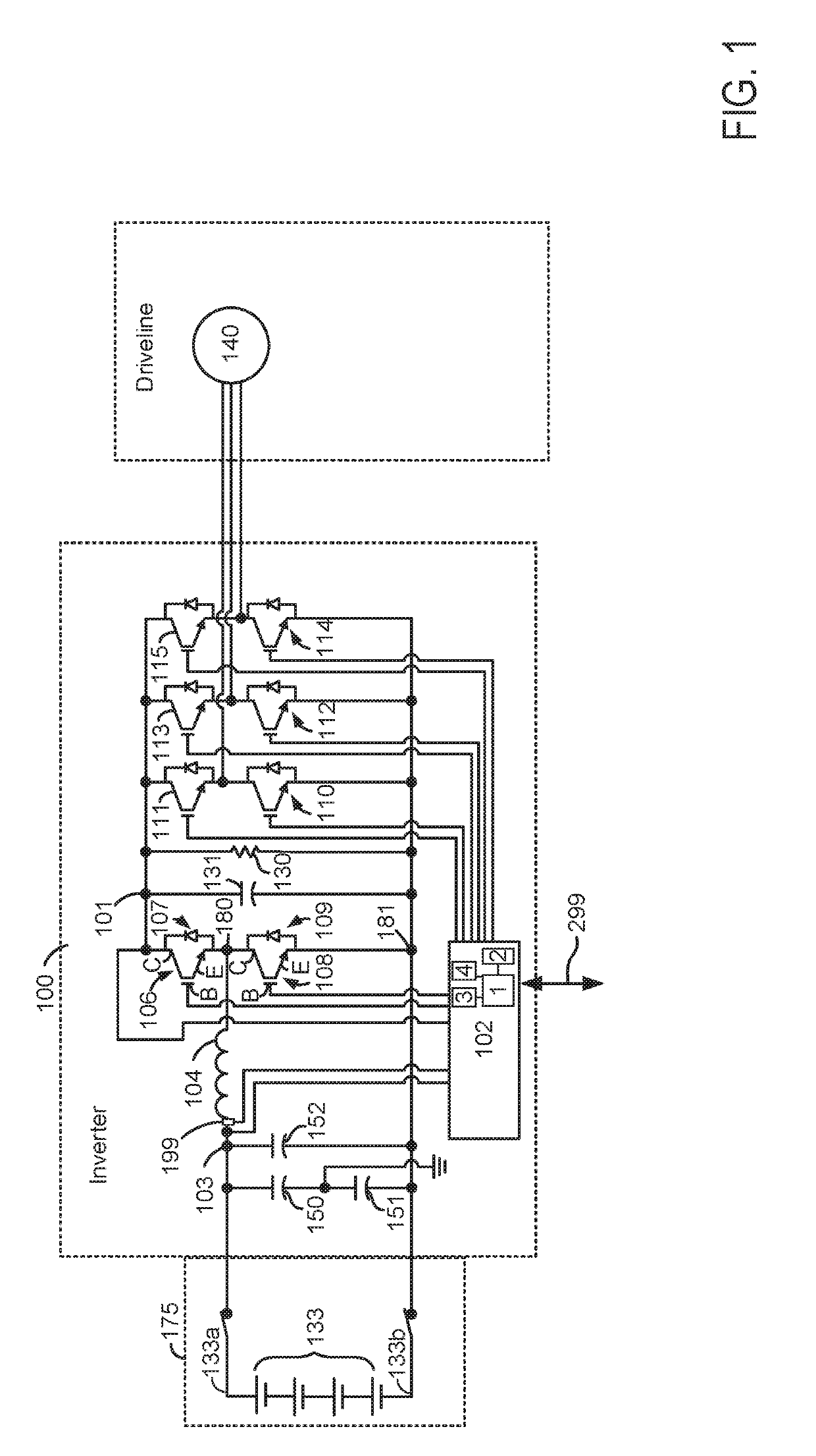
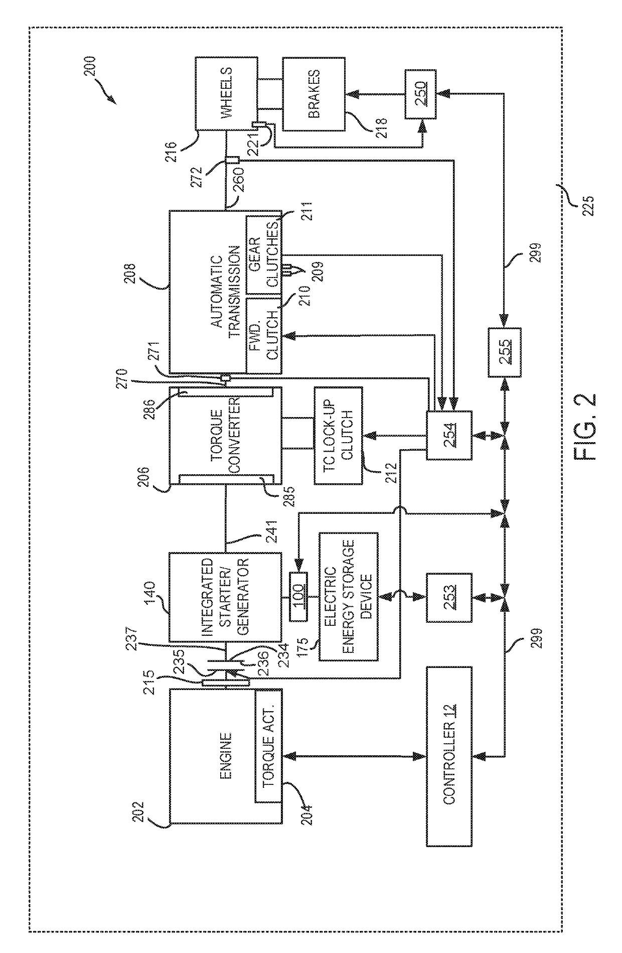
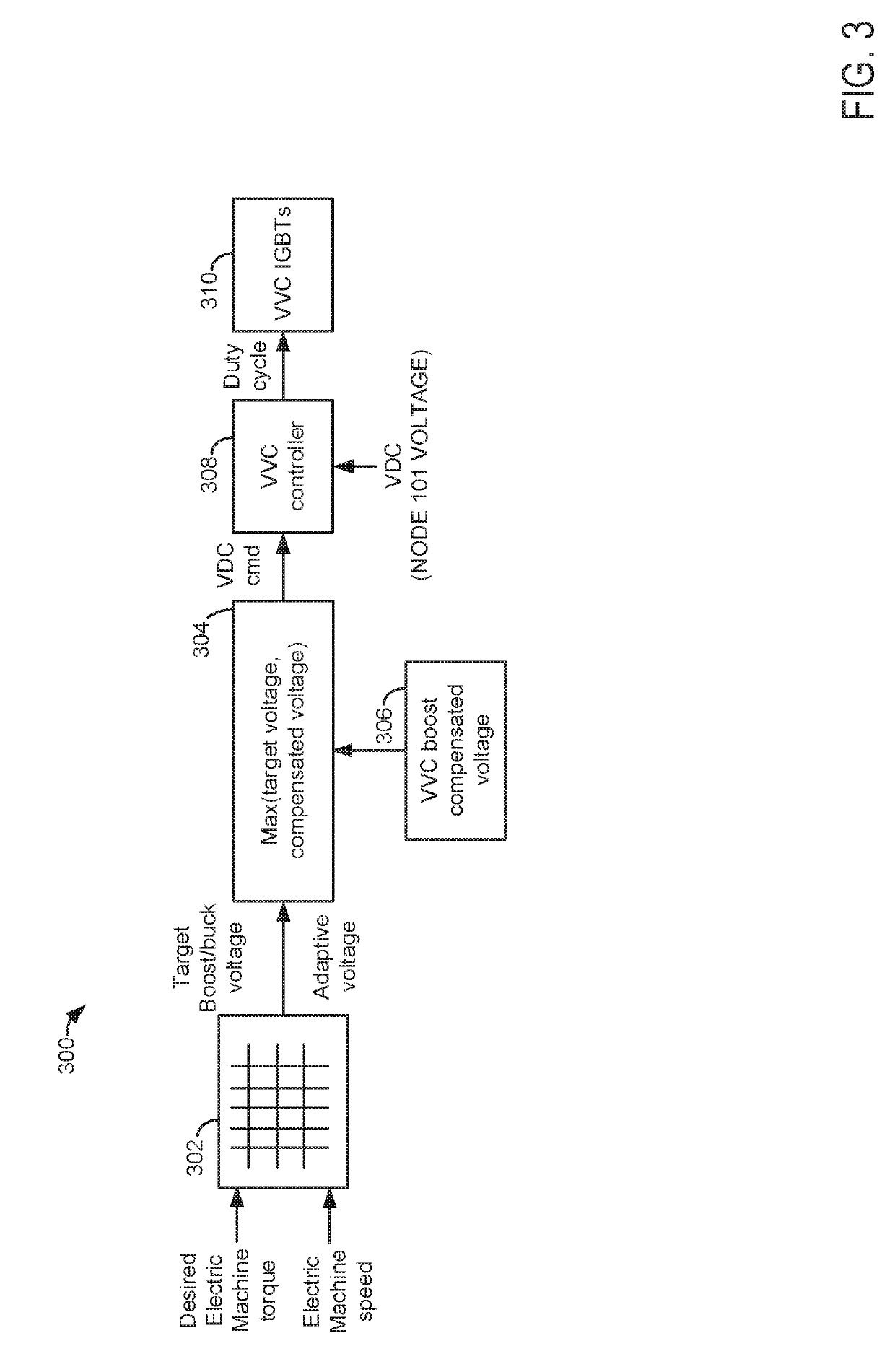
[0015]The present description is related to operating a variable voltage control inverter of a vehicle that includes an electric machine to provide effort to propel the vehicle and effort to decelerate the vehicle. The inverter may be configured as shown in FIG. 1. The inverter may be included in a vehicle driveline as shown in FIG. 2. The inverter may be operated via a controller as shown in FIG. 3. Voltage output of the inverter may be adjusted responsive to a dead time between boost transistor deactivation and buck transistor activation or a dead time between buck transistor deactivation and boost transistor activation as shown in FIG. 4. The inverter may be operated in a boost mode according to the method of FIG. 5 and the inverter may be operated in a buck mode according to the method of FIG. 6.

[0016]Referring to FIG. 1, inverter 100 is shown electrically coupled to electric energy storage device 175 (e.g., battery). In this example, electric energy storage device includes a pl...


PUM


Abstract

Systems and methods for operating an inverter that is electrically coupled to a battery and an electric machine that provides propulsive force to vehicle are described. The systems and methods may selectively adjust a duty cycle of an inverter transistor responsive to battery voltage and a dead time between when a first transistor is deactivated and when a second transistor is activated.

Description

FIELD[0001]The present description relates to methods and a system for operating a variable voltage control inverter of an electric only vehicle or a hybrid vehicle. The methods and systems may be particularly useful for vehicles that adjust boost voltage or buck voltage to provide a desired propulsion motor torque or to provide regeneration capability.BACKGROUND AND SUMMARY[0002]A vehicle may include an electric machine to provide propulsive torque to accelerate the vehicle. The electric machine may also provide a braking torque to the vehicle whereby the vehicle's kinetic energy may be converted into electric energy and stored for subsequent use. The electric machine may be electrically coupled to a battery or other electric energy storage device via an inverter. The inverter may convert direct current (DC) from the battery into alternating current (AC) to power the electric machine. Alternatively, the inverter may convert alternating current into direct current to charge the batt...

Claims


Application Information

Patent Timeline
Patent Type & Authority Applications(United States)
IPC IPC(8): B60W20/14B60L11/12B60W10/08B60W30/18
CPCB60W20/14B60L11/12B60W10/08B60W30/18127B60L2210/42B60W2510/083B60W2510/18H02J7/00H02M7/797H02J2207/20H02M1/38H02M3/158H02M1/007Y02T10/70B60L50/15
Inventor WANG, JIYAOSUN, FELICIA
Owner FORD GLOBAL TECH LLC
Learn More