Device housing a battery and charging pad

a battery and charging pad technology, applied in the direction of transformers, inductances, transportation and packaging, etc., can solve the problems of difficult to accurately transmit rapidly varying battery data in real-time, complex structure to transmit battery information from the battery-side to the power supply-side, etc., to achieve efficient battery charging, efficient battery connection or disconnection, and efficient power transmission

Inactive Publication Date: 2010-12-16
SANYO ELECTRIC CO LTD
View PDF13 Cites 78 Cited by
  • Summary
  • Abstract
  • Description
  • Claims
  • Application Information

AI Technical Summary

Benefits of technology

[0011]In the device housing a battery and charging pad of the present invention, the detection circuit 17 can detect receiving coil 51 impedance changes to detect battery information from either transmitting coil 11 voltage changes, current level changes, current-voltage phase relation changes, or transmission efficiency changes. As a result of the circuit structure, the charging pad can accurately detect connection or disconnection of the impedance modulating capacitor to the receiving coil by changes in various transmitting coil parameters.
[0012]In the device housing a battery and charging pad of the present invention, a series capacitor 55 can be connected in series with the receiving coil 51. With this circuit structure, battery information can be transmitted while efficiently transmitting power from the transmitting coil to the receiving coil for efficient battery charging. This is because for high current transmission, power transmission is more efficient with a capacitor connected in series with the receiving coil than with a capacitor connected in parallel. Further, power is normally transmitted to the receiving coil with a series-connected capacitor, and the low capacitance impedance modulating capacitor is only connected in parallel for extremely short time periods to transmit battery information.

Problems solved by technology

However, this configuration has the drawbacks that the circuit structure to transmit battery information from the battery-side to the power supply-side is complex, and it is difficult to accurately transmit rapidly varying battery data in real-time.

Method used


Image

  • Device housing a battery and charging pad
  • Device housing a battery and charging pad
  • Device housing a battery and charging pad

Examples


Embodiment Construction

)

[0033]The following describes embodiments of the present invention based on the figures.

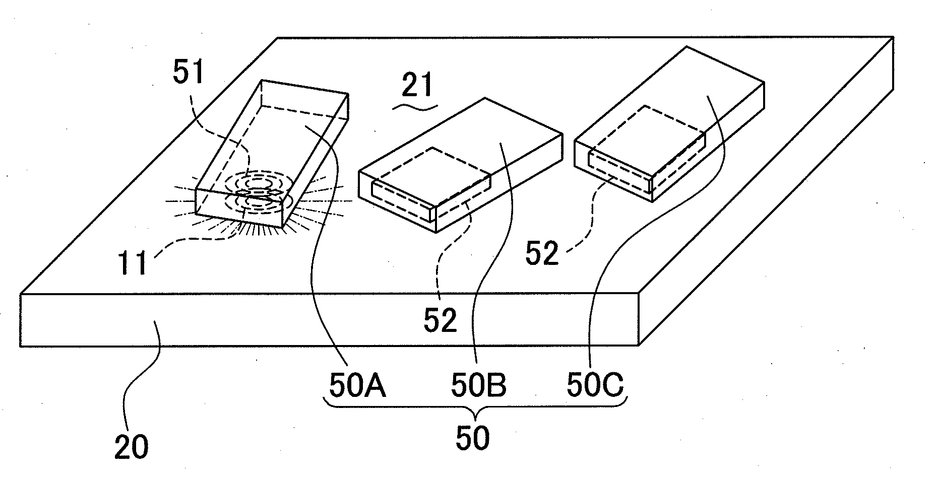
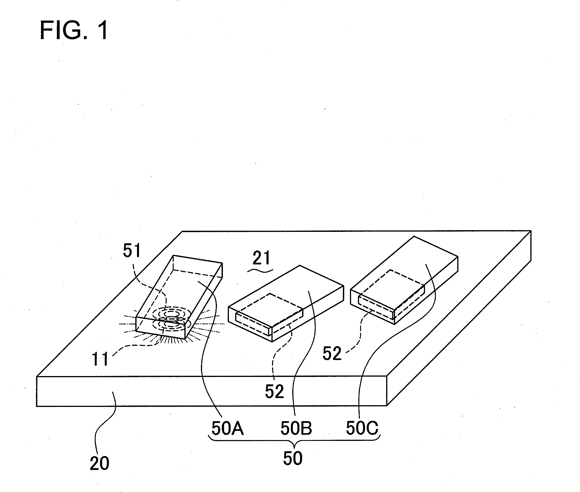
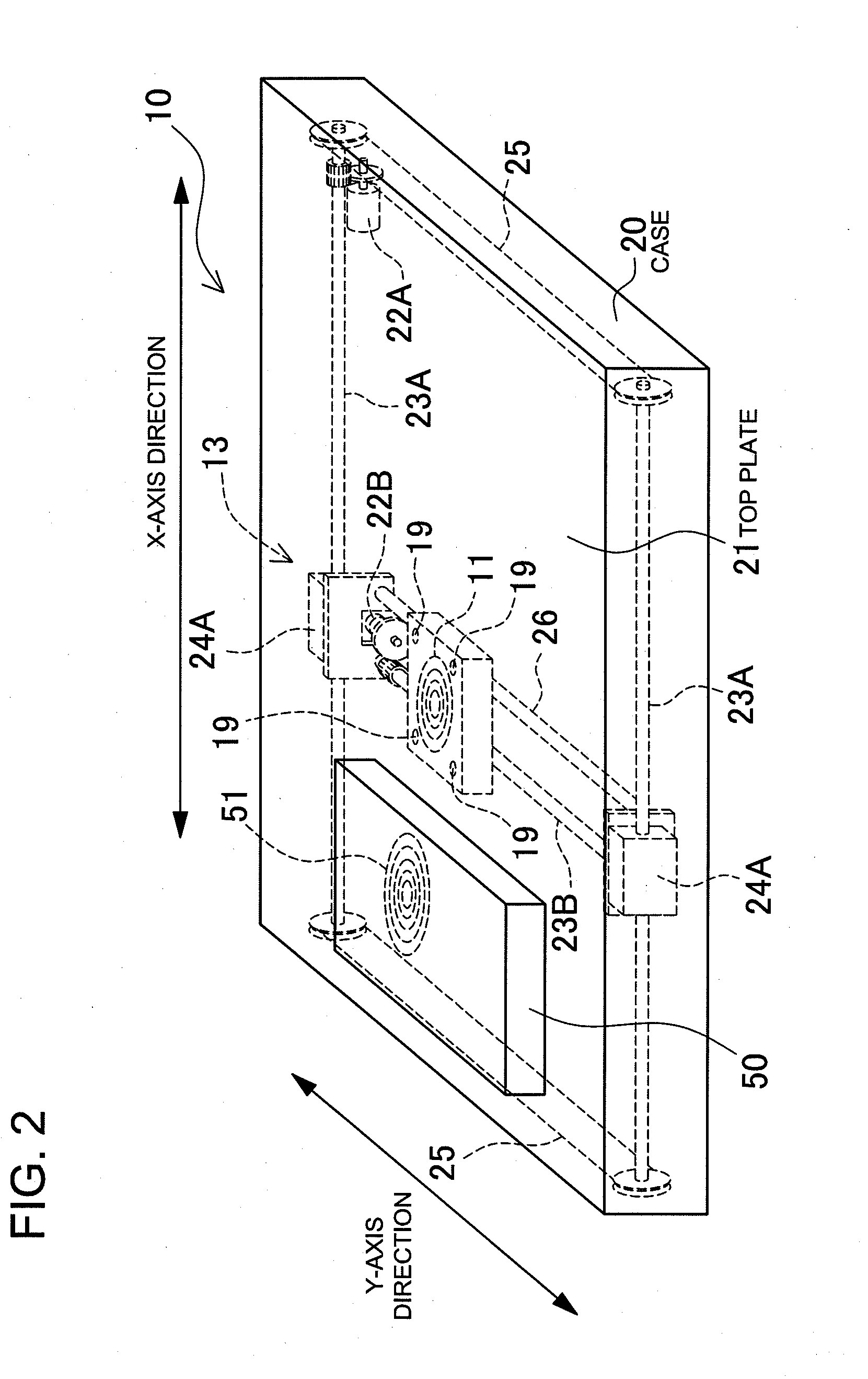
[0034]FIGS. 1-7 are schematic and diagrammatic views illustrating the structure and operating principles of the charging pad 10. As shown in FIGS. 1, 2, and 7, devices housing a battery 50 are placed on the charging pad 10, and the internal battery 52 is charged utilizing magnetic induction. A device housing a battery 50 contains a receiving coil 51 that magnetically couples with the transmitting coil 11, and a battery 52 that is charged by power induced in the receiving coil 51.

[0035]The device housing a battery 50 is provided with a modulator circuit 61 that changes the impedance of the receiving coil 51 according to internal battery 52 information. The charging pad 10 is provided with a detection circuit 17 that detects receiving coil 51 impedance changes made by the modulator circuit 61 to detect battery information via the transmitting coil 11.

[0036]The modulator circuit 61 is provided with...


PUM

PropertyMeasurementUnit
lengthaaaaaaaaaa
diameteraaaaaaaaaa
delay timeaaaaaaaaaa

Abstract

A device housing a battery 50 includes a receiving coil 51, and a charging pad 10 includes a transmitting coil 11 that magnetically couples with, and supplies charging power to the receiving coil 51. The device further includes a modulator circuit 61 that changes the impedance of the receiving coil according to internal battery 52 data. The charging pad further includes a detection circuit 17 that detects receiving coil impedance changes to detect the battery data. The modulator circuit 61 has a load circuit 62 that is connected in parallel with the receiving coil 51 and has a series-connected switching device 64 and impedance modulating capacitor 63, and a control circuit 65 that switches the load circuit 62 switching device 64 ON and OFF according to the battery data. The modulator circuit 61 switches the switching device 64 ON and OFF to transmit battery data to the charging pad 10.

Description

BACKGROUND OF THE INVENTION[0001]1. Field of the Invention[0002]The present invention relates to a device housing a battery (or batteries) such as a battery pack or mobile telephone, and to a charging pad that transmits power by magnetic induction to the device housing a battery to charge the battery inside.[0003]2. Description of the Related Art[0004]A charging pad (charging stand, charging cradle) has been developed to charge a battery housed in a device by transmitting power from a transmitting coil (power supply coil, primary coil) to a receiving coil (induction coil, secondary coil) by magnetic induction. (Refer to Japanese Laid-Open Patent Publication H09-63655 (1997).)[0005]JP H09-63655A cites a configuration with a charging pad housing a transmitting coil driven by an alternating current (AC) power source, and a battery pack containing a receiving coil that magnetically couples with the transmitting coil.[0006]The battery pack houses circuitry to rectify AC power induced in ...

Claims


Application Information

Patent Timeline
Patent Type & Authority Applications(United States)
IPC IPC(8): H02J7/00H01F38/14
CPCH01F38/14H02J7/025H02J50/40H02J50/90H02J50/80H02J50/12
Inventor TERAO, KYOZOTOYA, SHOICHI
Owner SANYO ELECTRIC CO LTD
Why Eureka
Try Eureka