Monolithic electrode, related material, process for production, and use thereof

a technology of monolithic electrodes and related materials, applied in the direction of non-aqueous electrolyte cells, cell components, electrochemical generators, etc., can solve the problems of limiting the energy density of the electrode, ultimately the energy density of the device, and the electrode charge/discharge rate, so as to improve the electrode cycle life, and improve the effect of electrode cycle li

Inactive Publication Date: 2011-11-17
SEYMOUR FRASER W
View PDF7 Cites 44 Cited by
  • Summary
  • Abstract
  • Description
  • Claims
  • Application Information

AI Technical Summary

Benefits of technology

[0021]The aforementioned need for improvements in electrode cycle life, operating voltage range and storage capacity for an EC device as well as improvements in electrode cycle life, reduced recharge times and increased usable storage capacity at elevated secondary battery power levels are provided by the use of an electrode material consisting of a highly porous carbon structure coated with a film comprising one or more transition metal oxides. The oxide film is simultaneously synthesized and deposited thereby forming a conformal oxide coating upon the highly porous carbon structure.
[0023]The openness of the material provides electrolyte ion access to the oxide film in a way that supports high rate ion transport with minimized ion starvation.
[0024]While many factors affect the rate of diffusion of an ion into a metal oxide during intercalation (approximately 10-9 cm2 / s for lithium into LiMnO2), it is clear such processes occur relatively slowly. Therefore, intercalation reaction rates are faster where diffusion lengths are shorter as is the case in thinner oxide layers. Due to the nanoscopic thin oxide film, the ion diffusion length is as much as two orders of magnitude less than that of typical oxide powder based films having micron-scale powder grains. The result is an enhanced rate of intercalation reaction versus powder oxide film approaches.
[0025]The carbon substrate exhibits a very high electronic conductivity of 20-50 Siemens / cm or more vs. 10−5 to 10−8 Siemens / cm for manganese oxide, depending upon the oxide phase. This reduction in electrode electronic resistance of between 5 and 8 orders of magnitude will greatly improve device power density and reduce heat generated.
[0026]The oxide exhibits increased capacity and a greater operating voltage range with improved stability vs. a single oxide film. For example, in the case of a nickel / manganese oxide, the partial substitution of the nickel oxide improves structural stability and provides an additional layered oxide phase improving ion vacancy access vs. a manganese-only oxide. Nickel / manganese oxide also has a higher theoretical capacity at a wider electrochemical potential than does manganese oxide alone so the resulting oxide will exhibit increased energy density. The partial substitution of a second transition metal oxide such as nickel for manganese in LiMn2O4 for example, provides an increase in redox potential.

Problems solved by technology

While the accessibility of the electrolyte to much of the surface area of such an electrode is limited, thus limiting the electrode capacitance and ultimately device energy density, the micropore geometries also serve to limit electrode charge / discharge rates and ultimately limit device power density.
In general, these oxides exhibit improved specific capacitance vs. carbon materials, but they typically do so at a monetary cost or at the expense of cycle life and power density.
However, the cost and lack of abundant supply of the ruthenium materials prohibit broad commercial use.
However, power density also is limited by the surface nature of pseudocapacitance as the longer ion diffusion length of thicker material serves to reduce reaction rate.
The power density of electrodes using these oxides is further limited by the very low intrinsic electronic conductivity of these materials.
These oxides also exhibit limited cycle stability and operating voltage ranges limited to approximately 0.8 volts.
The resulting electrode is limited by the characteristics noted above and also the lack of surface area readily accessible to the electrolyte.
The limited pore volume also impedes ion flow to the inner electrode surfaces further limiting the pseudocapacitance reaction rate.
One drawback to this type of asymmetric EC approach is that the cell must be maintained at a voltage level no less than approximately half the rated cell voltage, creating a potential safety hazard.
Further, limiting the operating voltage range of the device serves to limit the usable energy as well as limit market applications of the device.
Unfortunately, its limited planar surface area makes it impractical as an EC electrode.
While each of these approaches offer improved rate performance resulting from the reduced ion diffusion length vs. the simple oxide paste electrodes, they do not resolve the underlying problems associated with electronic conductivity and electrolyte accessibility.
While Long's approach does improve many of the shortcomings of the oxide as an EC electrode active material, it is limited to the formation of a MnO2 or iron oxide only film.
These expansion / contraction cycles cause the eventual breakdown of the oxide limiting device cycle life.

Method used


Image

  • Monolithic electrode, related material, process for production, and use thereof
  • Monolithic electrode, related material, process for production, and use thereof
  • Monolithic electrode, related material, process for production, and use thereof

Examples


example i

Fabrication of Electrode; Birnessite Manganese / Nickel Oxide Film on Carbon Nanofoam

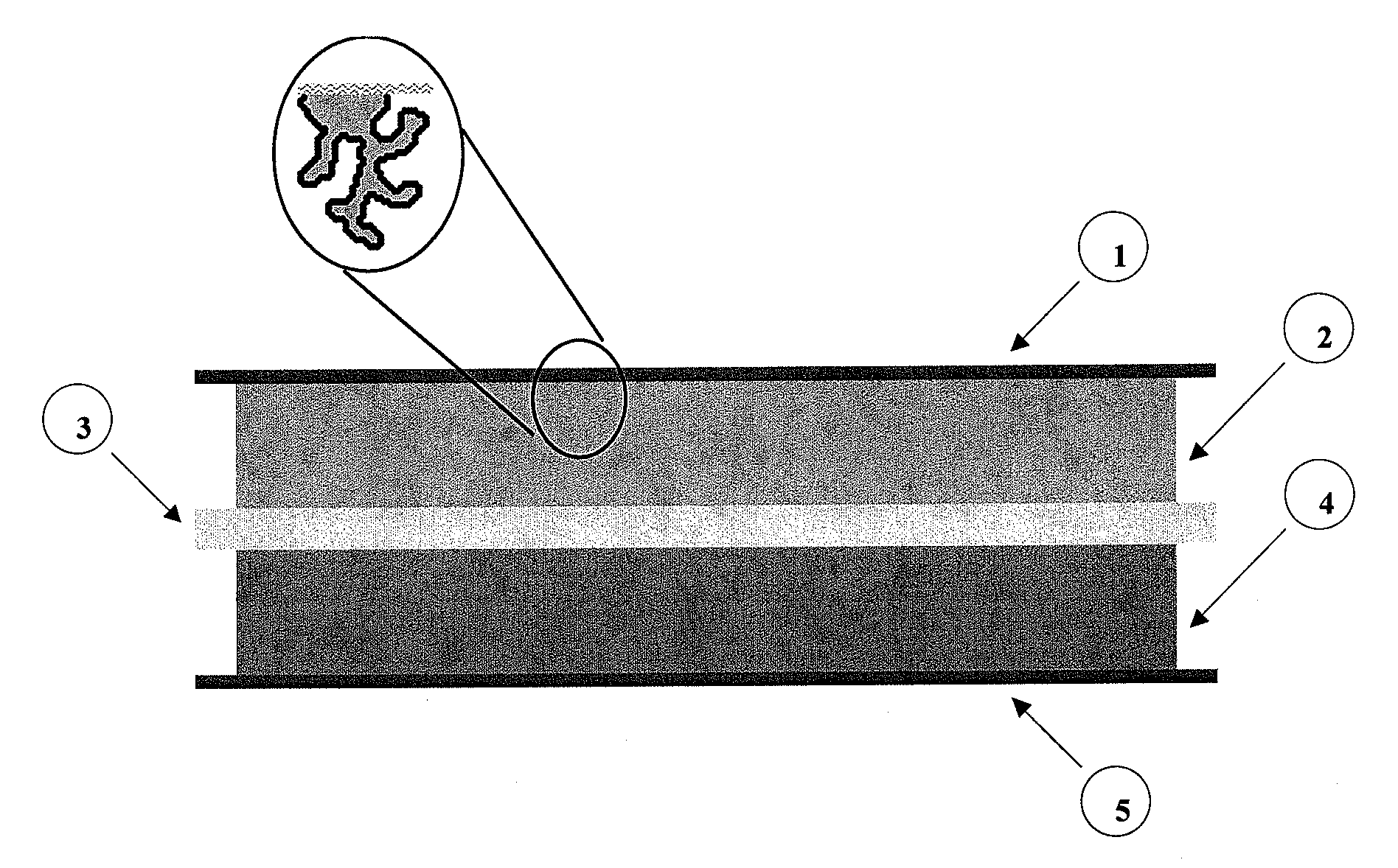
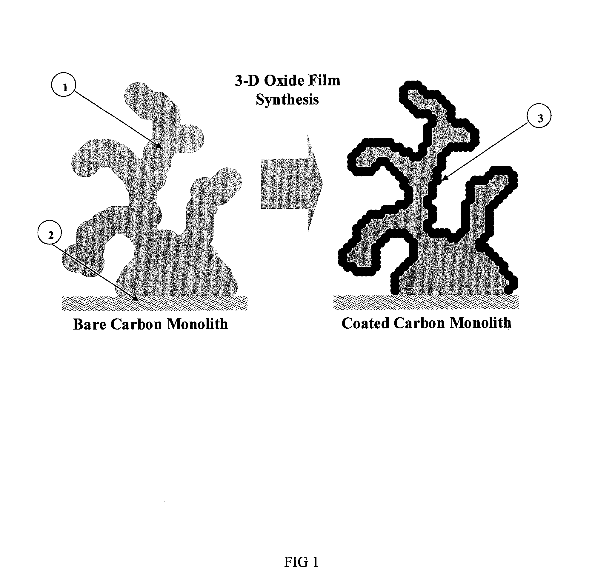
[0044]An electrode material as illustrated in FIG. 1 was formed by immersing a carbon structure for a controlled period of time in a solution comprising permanganate and nickel salts in a controlled ratio dissolved in ultra-pure water / pH buffer at a controlled pH and temperature. The manganese and nickel from the aqueous permanganate / nickel precursor solution are reduced on the surface of the carbon and co-deposited upon the carbon forming an insoluble oxide film.

[0045]Carbon paper and aerogel (“nanofoam”) was purchased from a commercial source (Marketech International Inc.) with an approximate thickness of 170 micrometers. Carbon nanofoam paper was cut into pieces of approximately 1 centimeter by 1 centimeter and then soaked and vacuum saturated in purified water.

[0046]In this exemplary embodiment, the aqueous metal salt precursor solution comprised manganese / nickel mixture ratios as follows: 4:1, 2:...

example ii

Characterization of Electrode Material; Manganese / Nickel Oxide Film on Carbon Nanofoam

[0049]The resulting electrode structure is shown in FIG. 4 scanning electronic micrograph image. This image clearly shows the material feature scale, the conformal oxide coating and the absence of pore occlusion.

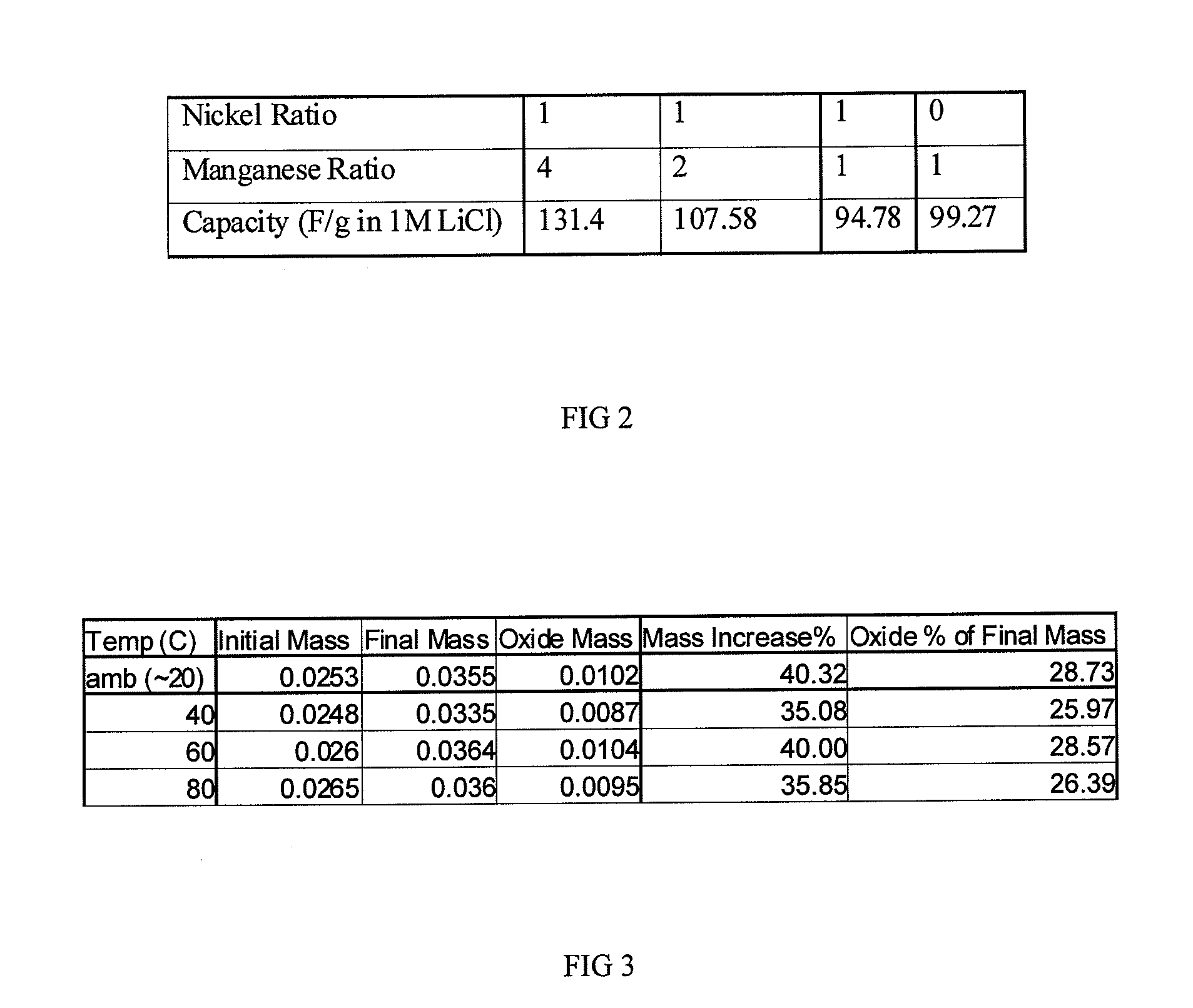
[0050]The table in FIG. 2 shows a 32% increase in capacitance of the 4:1 manganese / nickel oxide (131.4 F / g) vs. the manganese only material (99.27 F / g) in 1M LiCl electrolyte. Subsequent experiments have yielded capacitances of 180 F / g for the 4:1 manganese / nickel oxide in this electrolyte and approximately 200 F / g in other electrolytes such as potassium hydroxide (KOH). FIG. 5 shows cyclic voltammetry data of a 4:1 manganese / nickel oxide material with capacitance of approximately 180 F / g in 1M LiCl electrolyte.

example iii

Fabrication of Electrode; Nanoscale Oxide Film Comprising Spinel Manganese Doped with Nickel on Carbon Nanofiber / Microfiber Supported Carbon Xerogel Structure

[0051]An electrode material is formed as in EXAMPLE I, using a precursor ratio of about 0.99:0.01 manganese:nickel.

[0052]Prior to drying, counter ions are exchanged for lithium ions by immersion of the formed electrode in an aqueous solution bearing lithium ions such as lithium nitrate, lithium sulfate or lithium hydroxide, for example. In this exemplary embodiment, lithium nitrate was used. Such immersion is carried out first under vacuum equilibration, then at room temperature or elevated temperature or under microwave heating, for example. In this exemplary embodiment, about 30° C. for about 2-4 hours was used.

[0053]The material was subsequently heated to about 300-350° C. under nitrogen atmosphere for about 1-2 hours, followed by heating at about 200-220° C. in air for about 3-6 hours.


PUM

PropertyMeasurementUnit
thicknessaaaaaaaaaa
thicknessaaaaaaaaaa
pore sizeaaaaaaaaaa

Abstract

An electrode material is created by forming a thin conformal coating of metal oxide on a highly porous monolithic carbon structure. The highly porous carbon structure performs a role in the synthesis of the oxide coating and in providing a three-dimensional, electronically conductive substrate supporting the thin coating of metal oxide. The metal oxide includes one or more metal oxides. The electrode material, a process for producing said electrode material, an electrochemical capacitor and an electrochemical secondary (rechargeable) battery using said electrode material is disclosed.

Description

CROSS-REFERENCE TO RELATED APPLICATIONS[0001]This application is a continuation-in-part U.S. application Ser. No. 12 / 015,839, filed on Jan. 17, 2008, and claims priority thereto; the foregoing application being incorporated herein by reference.FIELD OF THE INVENTION[0002]The present invention relates to a material for use as an electrode for electrochemical energy storage devices such as electrochemical capacitors (ECs) and secondary batteries, and a method for producing the same. More specifically, this invention relates to an electrode material consisting of a highly porous carbon structure coated with a conformal film comprising one or more transition metal oxides, a method for producing the same, and an EC and secondary battery using the electrode materials.BACKGROUND OF THE INVENTION[0003]Electrochemical capacitors (referred to as ultracapacitors or supercapacitors) are devices that use electrolytes that contain and conduct ions in conjunction with electrodes that are ionically...

Claims


Application Information

Patent Timeline
Patent Type & Authority Applications(United States)
IPC IPC(8): H01M10/0565B32B3/26H01G9/00H01M10/0566B05D5/12B82Y99/00
CPCH01G11/36H01G11/46H01M4/364H01M4/366H01M4/48H01M4/50Y02E60/13H01M4/625H01M4/70H01M2004/021H01G11/24H01G11/32H01M4/52Y02E60/10Y10T428/249979
Inventor SEYMOUR, FRASER W.
Owner SEYMOUR FRASER W
Why Eureka
Try Eureka