
Z-axis motion system for a wire bonding machine

a motion system and wire bonding machine technology, applied in the direction of auxillary welding devices, magnetic bodies, soldering apparatuses, etc., can solve the problems of insufficient provision of desirable features of conventional motors, impractical reduction of fixed current errors, and more powerful motors

Inactive Publication Date: 2011-05-19
KULICKE & SOFFA IND INC
View PDF3 Cites 2 Cited by
  • Summary
  • Abstract
  • Description
  • Claims
  • Application Information

AI Technical Summary

Benefits of technology

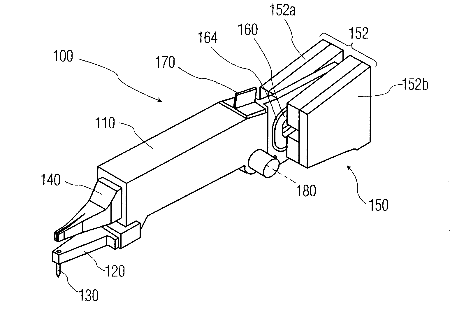
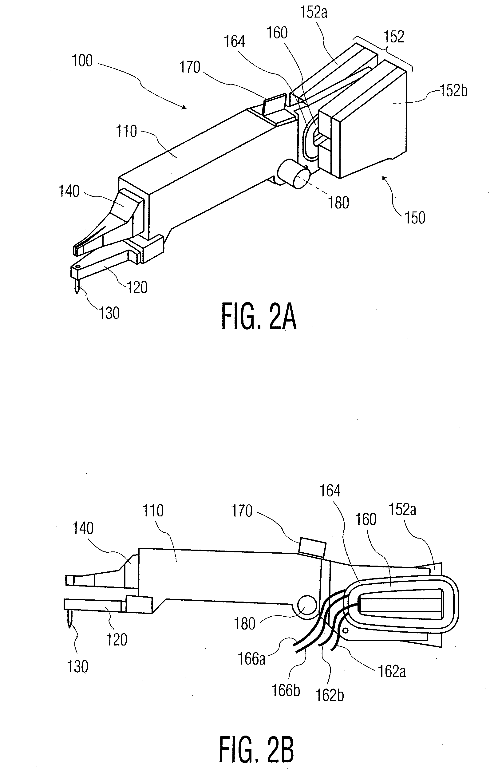
[0041]By separating the z-axis force control between different coil portions in accordance with certain exemplary embodiments of the present invention, a number of advantages are achieved. For example, a higher maximum z-motor force (with increased acceleration for high speed motions) is provided, while at the same time, finer control of the z-motor force is also provided for bond force accuracy and the like. More specifically, the force constant of a larger coil portion (or in certain embodiments, the complete coil) can be raised in comparison to prior z-axis coils without adversely affecting the force accuracy for relatively static forces such as bond forces because of the inclusion of a smaller coil portion.

Problems solved by technology

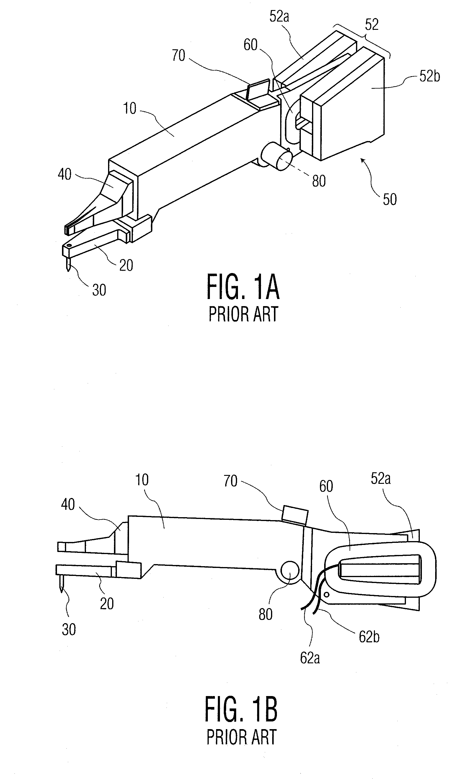
Unfortunately, conventional motors do not adequately provide for these desirable features.
For example, a small error in applied current with respect to the total current range may be a large portion of the desired current during bond force control.
Further, it may be impractical to reduce such fixed current errors (e.g., an error caused by thermal drift in the motor amplifier) to a sufficiently low level to achieve the desired bond force accuracy with a motor that is also suitable for high speed motions.
Further still, more powerful motors (e.g., motors that are desirable for high acceleration and motion performance) tend to have correspondingly larger force errors due to the fixed current errors.

Method used


Image

  • Z-axis motion system for a wire bonding machine
  • Z-axis motion system for a wire bonding machine
  • Z-axis motion system for a wire bonding machine

Examples


Embodiment Construction

[0027]According to the present invention, an improved coil assembly for the z-axis of a wire bonding machine is provided.

[0028]In the present application a system for moving a bonding tool along a substantially vertical axis (e.g., the z-axis) is provided. Often, the motion along the substantially vertical axis is provided by a pivoting motion of a bond head assembly or the like (which supports the bonding tool), where the pivoting motion of the bond head assembly with respect to a support structure of a wire bonding machine results in substantially vertical motion of the bonding tool; however, the present application also contemplates other motions than pivoting motions (e.g., a linear motion) of the bond head assembly to provide the substantially vertical motion of the bonding tool.

[0029]According to an exemplary embodiment of the present invention, the force accuracy of a z-axis motor is improved, without a corresponding increase in dynamic range or accuracy of the current suppli...


PUM

PropertyMeasurementUnit
force constantaaaaaaaaaa
electricallyaaaaaaaaaa
bonding forceaaaaaaaaaa

Abstract

A coil assembly configured to provide motion of a bonding tool of a wire bonding machine along a substantially vertical axis is provided. The coil assembly includes a first coil portion having a first force constant, the first coil portion being configured to receive energy to provide a first motion of the bonding tool. The coil assembly also includes a second coil portion having a second force constant, the second coil portion being configured to receive energy to provide a second motion of the bonding tool, the second force constant being different from the first force constant.

Description

CROSS-REFERENCE[0001]The present application is a divisional application of U.S. patent application Ser. No. 11 / 817,882 filed on Sep. 6, 2007, which is a U.S. National Phase Application of PCT Application No. PCT / US2006 / 033852 filed on Aug. 30, 2006, the content of both of which is incorporated herein by reference in its entirety.FIELD OF THE INVENTION[0002]The present invention relates to wire bonding of semiconductor devices, and more particularly, to providing an improved z-axis motion system for a wire bonding machine.BACKGROUND OF THE INVENTION[0003]Wire bonders (i.e., wire bonding machines) typically include a vertical or substantially vertical motion axis that carries components such as a bonding tool (e.g., a capillary tool), an ultrasonic transducer (if used), a wire clamp, etc. This motion axis is commonly referred to as the “z-axis” and is utilized to position the bonding tool for bonding, looping, ball formation (e.g., via electric flame-off, etc.), and is also utilized ...

Claims


Application Information

Patent Timeline
Patent Type & Authority Applications(United States)
IPC IPC(8): B23K20/10
CPCB23K20/004H01F7/064H01F7/1615H01F2007/1692H01L21/67138H01L2224/78301H01L2924/00014H01L2224/85205H01L2924/19042H01L24/78H01L2224/48H01L2224/45099
Inventor SCHMIDT-LANGE, MICHAEL P.JAESCHKE, STEPHEN M.
Owner KULICKE & SOFFA IND INC
Learn More