Terminating type switch-over connector

A transfer connector and termination technology, applied in the direction of connection, connecting device parts, contact parts, etc., can solve the problems of easy damage of electrical connectors, and achieve the effect of reducing fatigue, dispersing bending stress, and solving easy damage.

Active Publication Date: 2015-04-15
CHINA AVIATION OPTICAL-ELECTRICAL TECH CO LTD
View PDF5 Cites 5 Cited by
  • Summary
  • Abstract
  • Description
  • Claims
  • Application Information

AI Technical Summary

Problems solved by technology

[0005] The purpose of the present invention is to provide a terminal transfer connector to so

Method used


Image

  • Terminating type switch-over connector
  • Terminating type switch-over connector
  • Terminating type switch-over connector

Examples


Embodiment Construction

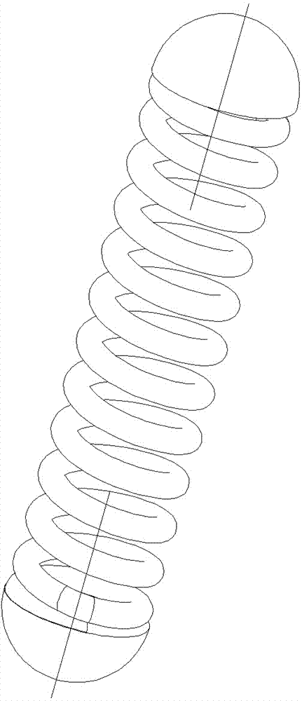
[0018] Examples of terminated transition connectors such as Figure 4-6 As shown, the terminating transfer connector includes a panel housing 101 and a contact member 102 .

[0019] The panel housing 101 is provided with a transparent mounting hole, and its structure is in the prior art, which will not be repeated here.

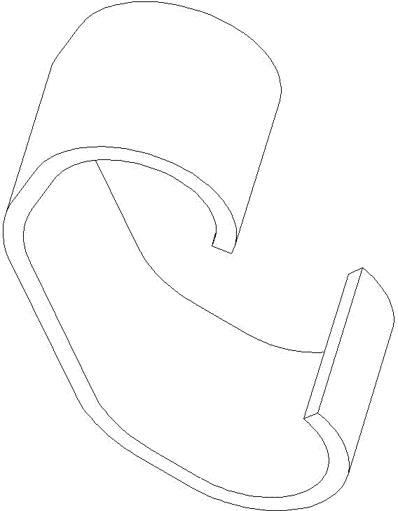
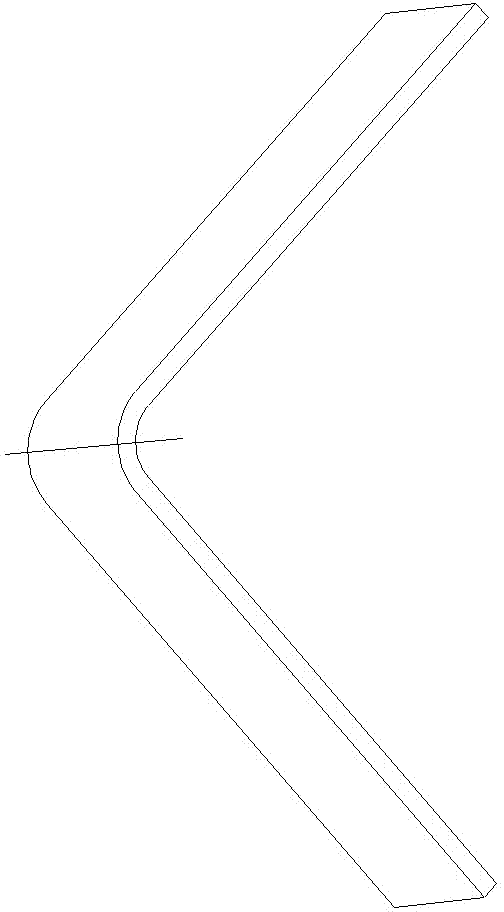
[0020] The contact piece 102 is disposed in the corresponding mounting hole on the panel housing, and is a reed contact piece, including two contact parts 11 at both ends and a connection part 12 connected between the two contact parts 11 .

[0021] The contact portion 11 is arc-shaped. In this embodiment, the contact portion 11 is arc-shaped. When in use, the outer surface of the arc top of the contact portion 11 can be used as a contact surface for contacting the adapter connector.

[0022] The connecting portion 12 is U-shaped. In this embodiment, the U-shape formed by the connecting portion 12 is not a standard U-shape. A U-shape with a tendency to be c...


PUM


Abstract

The invention relates to the field of electric connectors, in particular to a terminating type switch-over connector. The terminating type switch-over connector comprises a faceplate shell. Through mounting holes are formed in the faceplate shell. Reed type contact pieces are arranged in the mounting holes. Each contact piece comprises two arc-shaped contact portions at two ends and a U-shaped connection portion connected between the two contact portions, wherein the contact portions and the connection portion are in arc transition connection and form a bow-shaped structure. During use, when contacting with an adaptive connector to be pressed, each contact piece at least comprises deformable portions including a U-shaped bending portion formed by the corresponding connection portion, transition positions between the contact portions and the connection portion and portions, close to the connection portion, of the contact portions, so that bending stress of the contact piece when the contact piece is pressed can be dispersed greatly, and fatigue of contact reeds is relieved. The terminating type switch-over connector solves the problem that electric connectors using the reed-type contact pieces are prone to damage.

Description

technical field [0001] The present invention relates to the field of electrical connectors, in particular to a terminal type transfer connector. Background technique [0002] Electrical connectors are commonly used components for electrical signal transmission, not only in communications, power transmission and other industries, but are now widely used in aerospace and other fields. In some special occasions, the contacts of the electrical connector do not use the conventional plug-in method, but use the elastic pressure contact method to transmit electrical signals. Such electrical connectors are often used for electrical signal transfer. It includes a panel, the panel is provided with a transparent mounting hole, an elastic contact piece in the mounting hole, and the two ends of the contact piece respectively form a contact portion, which is elastically contacted with components such as the conductive plate of the adapting electrical connector when in use. Realize the tr...

Claims


Application Information

Patent Timeline
IPC IPC(8): H01R13/24H01R31/06
CPCH01R13/2414H01R13/2428H01R31/06
Inventor 周国奇张磊张晓光
Owner CHINA AVIATION OPTICAL-ELECTRICAL TECH CO LTD
Why Eureka
Try Eureka