U-shaped support punching blanking bending composite die

A technology of punching blanking and composite molds, which is applied in the field of mechanical processing, can solve the problems of reducing work efficiency, increasing human resources, increasing production time, etc., and achieves the effects of high production efficiency, high economic benefits, and less process equipment

Inactive Publication Date: 2015-04-22
李俊
View PDF0 Cites 17 Cited by
  • Summary
  • Abstract
  • Description
  • Claims
  • Application Information

AI Technical Summary

Problems solved by technology

[0002] Generally, U-shaped bracket parts can only be completed by punching and blanking first, then bending or bending first, and then punching and blanking. This process requires more equipment and labor, and consumes a lot of energy. Due to the variety of processe

Method used


Image

  • U-shaped support punching blanking bending composite die

Examples


Example Embodiment

[0009] The specific implementation manners of the present invention will be described in further detail below in conjunction with the accompanying drawings.

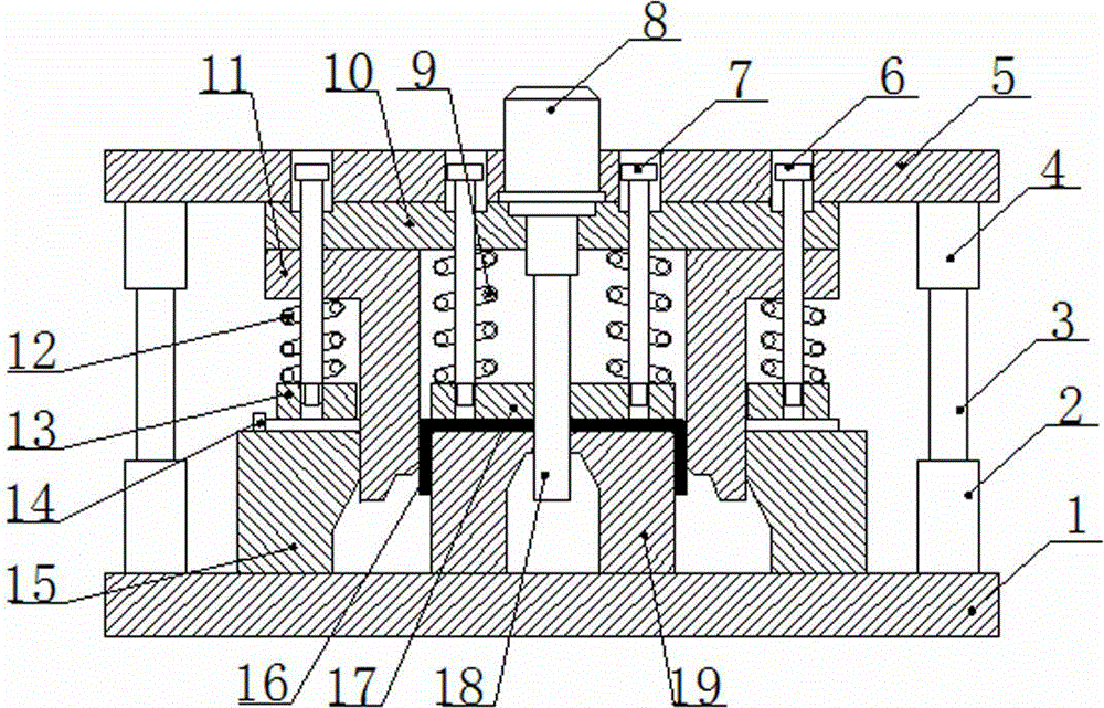
[0010] A U-shaped bracket punching blanking bending composite mold such as figure 1 As shown, it includes: upper mold base 5, fixed wedge plate 11; spring 12, mold handle 8, pull rod 6, mounting plate 10, sheet material, guide post 3, die 15, lower guide sleeve 2, lower mold base 1, Spring 9, pull rod 7, forming punch 19, binder plate 17, positioning pin 14, punching punch 18, upper guide sleeve 4, pressing block 13 and workpiece 16. The upper die base 5 lower end is provided with mounting plate 10, is provided with die 15 between mounting plate 10 and lower die base 1, and the bottom of die base 15 is fixed with lower die base 1, and the top of die base 15 is provided with sheet material, One end of the plate is provided with a positioning pin 14, the positioning pin 14 is connected with the die 15, the wedge plate 11 ...


PUM


Abstract

The invention discloses a U-shaped support punching blanking bending composite die. Blanking, bending and punching of a U-shaped support are completed through one die, production efficiency is high, used process devices are few, economic benefit is high, and the problem that an existing U-shaped support needs a blanking die, a bending die and a punching die and low production efficiency, large process device number and low economic benefit are caused is solved.

Description

technical field [0001] The invention relates to the field of mechanical processing, in particular to a U-shaped bracket punching, blanking and bending composite mold. Background technique [0002] Generally, U-shaped bracket parts can only be completed by punching and blanking first, then bending or bending first, and then punching and blanking. This process requires more equipment and labor, and consumes a lot of energy. Due to the variety of processes, Each process has a certain error, so the cumulative error of the product is relatively large, and if punching and blanking are performed first and then bent, human resources will be increased, production time will be increased, and work efficiency will be reduced. Contents of the invention [0003] The purpose of the present invention is to provide a U-shaped support punching, blanking and bending composite mold, which can complete the punching, blanking and bending of the U-shaped support at one time, thereby ensuring the...

Claims


Application Information

Patent Timeline
IPC IPC(8): B21D37/12B21D28/14B21D28/34
CPCB21D37/10B21D35/002
Inventor 李俊
Owner 李俊
Why Eureka
Try Eureka