Fixed wheel assembly of pipe bending machine

A technology of pipe bending machine and fixed wheel, which is applied in positioning device, metal processing equipment, feeding device, etc., can solve the problems of poor compatibility of pipe fittings, low work efficiency, poor work stability, etc., and achieves low cost, improved work efficiency, simple structure

Active Publication Date: 2015-04-22
无锡晶瑜智能机械有限公司
View PDF5 Cites 1 Cited by
  • Summary
  • Abstract
  • Description
  • Claims
  • Application Information

AI Technical Summary

Problems solved by technology

[0003] In the prior art, in the process of using the traditional pipe bending machine, there are problems such as low working efficiency, poor working stability, easy damage to parts, etc., and poor compatibility for bending pipe fittings of different sizes

Method used


Image

  • Fixed wheel assembly of pipe bending machine

Examples


Embodiment Construction

[0013] Below the present invention will be further described in conjunction with the embodiment in the accompanying drawing:

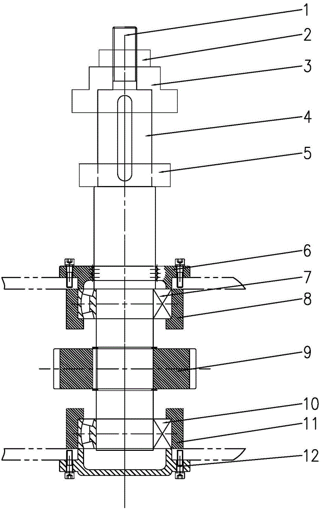
[0014] Such as figure 1 Shown, the present invention mainly comprises fixed wheel shaft 4, and fixed wheel shaft 4 bottoms are provided with fixed gear 9, and when working, drive fixed wheel shaft 4 to rotate by gear transmission.

[0015] The upper part of the fixed wheel shaft 4 is sequentially connected with the upper platen 3 and the lower pallet 5 from top to bottom. hold. By adjusting the distance between the upper platen 3 and the lower pallet 5, the bending requirements of workpieces of different sizes can be met.

[0016] The upper end of the upper pressure plate 3 is connected to the fixed shaft 1, and the fixed shaft 1 is connected to the tightening ring 2, and the upper pressure plate 3 is compressed by the tightening ring 2.

[0017] On the fixed wheel shaft 4, the upper bearing seat 8 and the lower bearing seat 11 are respectively conn...


PUM


Abstract

The invention relates a fixed wheel assembly, specifically relates to a fixed wheel assembly of a pipe bending machine, and belongs to the technical field of pipe bending machines. The fixed wheel assembly of the pipe bending machine comprises a fixed wheel shaft; a fixed gear is arranged at the lower part of the fixed wheel shaft; an upper pressing plate and a lower supporting plate are connected to the upper part of the fixed wheel shaft from top to bottom in a sequence; the fixed wheel is respectively connected with an upper bearing block and a lower bearing block through an upper bearing and a lower bearing; the upper bearing block and the lower bearing block are respectively positioned at the upper end and the lower end of the fixed gear. The fixed wheel assembly of the pipe bending machine is simple, compact and reasonable in structure; when in working, a workpiece is clamped through the upper pressing plate and the lower supporting plate, so that the pipe bending machine can stably work for bending, the working efficiency is increased, and the cost is relatively low; the distance from the upper pressing plate to the lower supporting plate can be adjusted to meet the requirement on bending the workpiece of different size, and therefore, the applicable scope is expanded.

Description

technical field [0001] The invention relates to a fixed wheel assembly, in particular to a fixed wheel assembly of a pipe bending machine, which belongs to the technical field of pipe bending machines. Background technique [0002] Pipe bending machines can be roughly divided into CNC pipe bending machines, hydraulic pipe bending machines and so on. The pipe bender mainly uses hydraulic pressure to perform winding bending of the pipe body with one or two bending radii in a cold state. It is widely used in the bending of various pipe fittings and wires in industries such as automobiles and air conditioners. [0003] In the prior art, the traditional pipe bending machine has problems such as low working efficiency, poor working stability, easy damage to parts, etc. during use, and poor compatibility for bending pipe fittings of different sizes. Contents of the invention [0004] The purpose of the present invention is to overcome the above disadvantages, thereby providing a...

Claims


Application Information

Patent Timeline
Patent Type & Authority Applications(China)
IPC IPC(8): B21D43/00B21D7/00
CPCB21D7/00B21D43/003
Inventor 赵军
Owner 无锡晶瑜智能机械有限公司
Why Eureka
Try Eureka