Steel bar bending machine

A machine and steel bar technology, applied in the field of steel bar bending machines, can solve problems such as low work efficiency and high safety hazards, and achieve the effect of improving work efficiency

Pending Publication Date: 2022-03-08
温新偶
View PDF0 Cites 0 Cited by
  • Summary
  • Abstract
  • Description
  • Claims
  • Application Information

AI Technical Summary

Problems solved by technology

[0005] In order to overcome the traditional steel bar bending equipment, the steel bar is manually placed on the equipment for bending, and the steel bar is usually taken out manually after the steel bar is bent, which has the disadvantages of low work efficiency and high potential safety hazards. The present invention The technical problem is: to provide a steel bar bending machine that can automatically advance and retreat materials and has a pressing function

Method used


Image

  • Steel bar bending machine
  • Steel bar bending machine
  • Steel bar bending machine

Examples


Embodiment 1

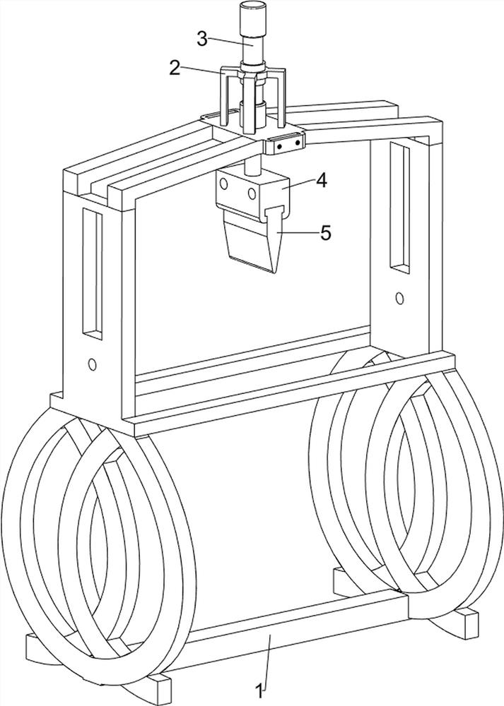
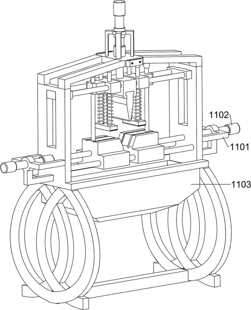
[0027] A steel bending machine, such as figure 1 , figure 2 and image 3 As shown, it includes a support frame 1, a first fixed frame 2, a first cylinder 3, a fixed block 4, a limit plate 5, a guide mechanism 6 and a clamping mechanism 7, and the top of the support frame 1 is provided with a first fixed frame 2, The first cylinder 2 is provided with a first cylinder 3 inboard, the piston rod of the first cylinder 3 is provided with a fixed block 4, the bottom of the fixed block 4 is provided with a limit plate 5, and the inner side of the support frame 1 top is provided with a guide mechanism 6, and the guide mechanism 6 is provided with clamping mechanism 7.

[0028] When it is necessary to bend the steel bar, people place the steel bar at the clamping mechanism 7, then start the first cylinder 3, and under the action of the piston rod of the first cylinder 3, drive the fixed block 4 and the limit plate 5 to move downward , so that the guide mechanism 6 drives the clampin...

Embodiment 2

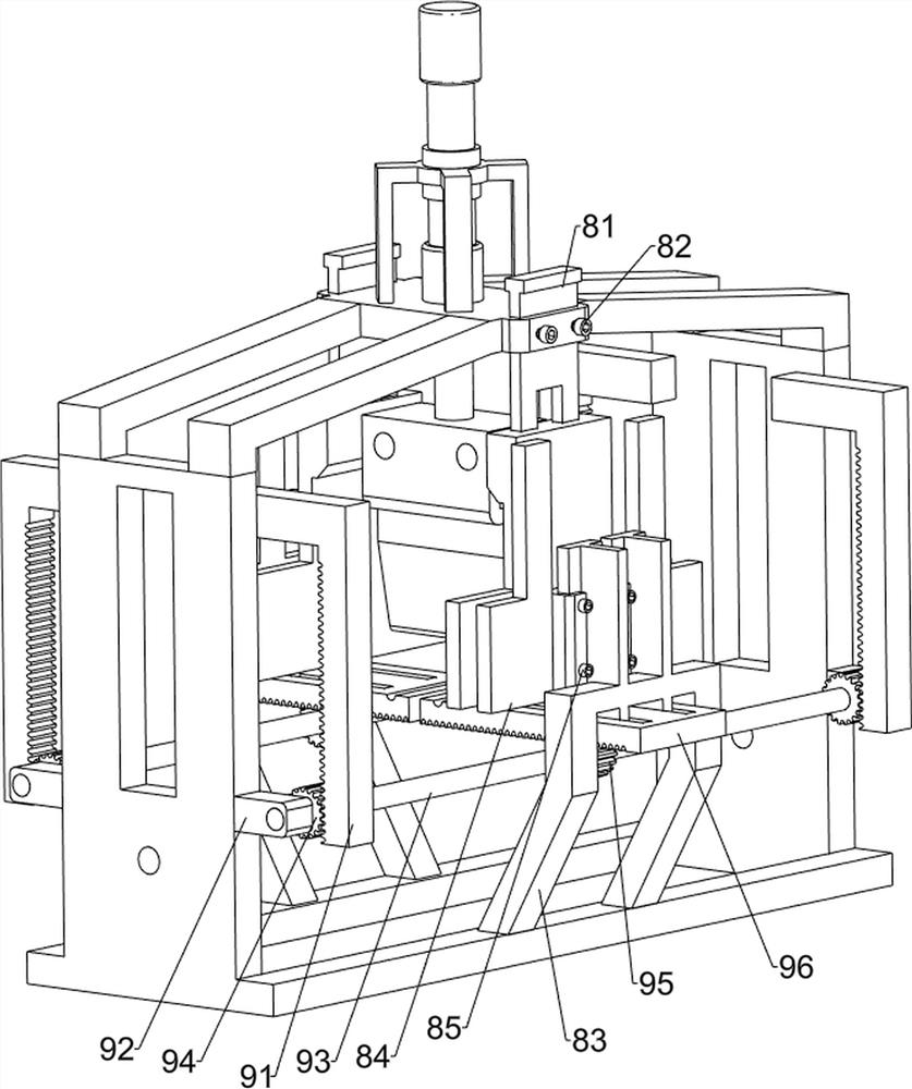
[0033] On the basis of Example 1, such as Figure 4 , Figure 5 , Figure 6 and Figure 7As shown, an adjustment mechanism 8 is also included. The adjustment mechanism 8 includes a first baffle plate 81, a first stop nut 82, a bracket 83, a second baffle plate 84 and a second limit nut 85. The side sliding type is provided with the first baffle plate 81, the front and rear sides of the top of the support frame 1 are symmetrically provided with the first stop nut 82 through threads, the front and rear sides of the middle part of the support frame 1 are provided with supports 83, and the inner sides of the upper part of the support frame 1 are all slidingly designed. There is a second baffle 84 , and the second baffle 84 is provided with six second limit nuts 85 through threads, and the second limit nuts 85 are all matched with the bracket 83 .

[0034] Also include feed mechanism 9, feed mechanism 9 includes first tooth bar 91, the 3rd limit block 92, transmission shaft 93, ...


PUM


Abstract

The invention relates to a bending machine, in particular to a steel bar bending machine. The technical problem of the invention is to provide the reinforcing steel bar bending machine which can automatically feed and discharge materials and has a pressing function. A steel bar bending machine comprises a supporting frame and a first fixing frame, and the first fixing frame is arranged at the top of the supporting frame. The first air cylinder is arranged on the inner side of the first fixing frame; the fixed block is arranged on a piston rod of the first air cylinder; the limiting plate is arranged at the bottom of the fixing block; the guide mechanism is arranged on one side in the supporting frame; and the clamping mechanism is arranged on the guide mechanism. Under the action of a piston rod of a first air cylinder, a fixing block is driven to move downwards, so that a first round rod and a sliding block are driven to move downwards, then a guide rod and a pressing plate are driven to move downwards, at the moment, the pressing plate tightly presses a reinforcing steel bar, and the reinforcing steel bar can be bent more stably.

Description

technical field [0001] The invention relates to a bending machine, in particular to a steel bar bending machine. Background technique [0002] Steel bar is steel for reinforced concrete and prestressed reinforced concrete. Steel bar is widely used in various construction industries, especially various large, heavy and light thin-walled building structures. [0003] Steel bar is a strip, which is a kind of building material. In reinforced concrete, it is used to support the structural skeleton. The steel bar is tensile but not compressive, and the concrete is compressive but not tensile. The combination of the two has good mechanical strength. Therefore, it has become an ideal material for modern buildings, and steel bar bending is used in major construction industries. At present, traditional steel bar bending equipment is to manually place steel bars on the equipment for bending, and after steel bar bending is completed, usually Also be that steel bar is taken out manually...

Claims


Application Information

Patent Timeline
IPC IPC(8): B21F1/00B21F23/00
CPCB21F1/004B21F23/00
Inventor 温新偶
Owner 温新偶
Why Eureka
Try Eureka