Workpiece clamping device of filament winder

A technology of clamping device and wire winding machine, which is applied in the field of workpiece clamping device, can solve the problems of low production efficiency, reduced production efficiency, time-consuming and laborious, etc., and achieve the effect of avoiding pinching the wire winding plate and high production efficiency

Inactive Publication Date: 2015-04-22
何雲彬
View PDF7 Cites 4 Cited by
  • Summary
  • Abstract
  • Description
  • Claims
  • Application Information

AI Technical Summary

Problems solved by technology

Because the cross-section of the wire wrapping plate is rectangular, the existing wire winding machines generally use a clamping device similar to a milling machine to clamp the wire wrapping plate. During production, the clamping device needs to be manually released and clamped, which is troublesome to operate. , time-consuming and labor-intensive, low production efficiency, and it is easy to damage the wire wrapping board due to excessive clamping force during manual clamping
[0003] In addition, in the existing wire winding machines, after the wire winding is completed, the electric heating plate is often disassembled, and then the resistance detection is performed manually to detect whether the resistance of the electric heating wire meets the standard, which further reduces the production efficiency

Method used


Image

  • Workpiece clamping device of filament winder
  • Workpiece clamping device of filament winder
  • Workpiece clamping device of filament winder

Examples


Embodiment Construction

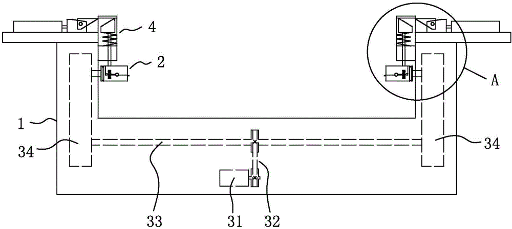
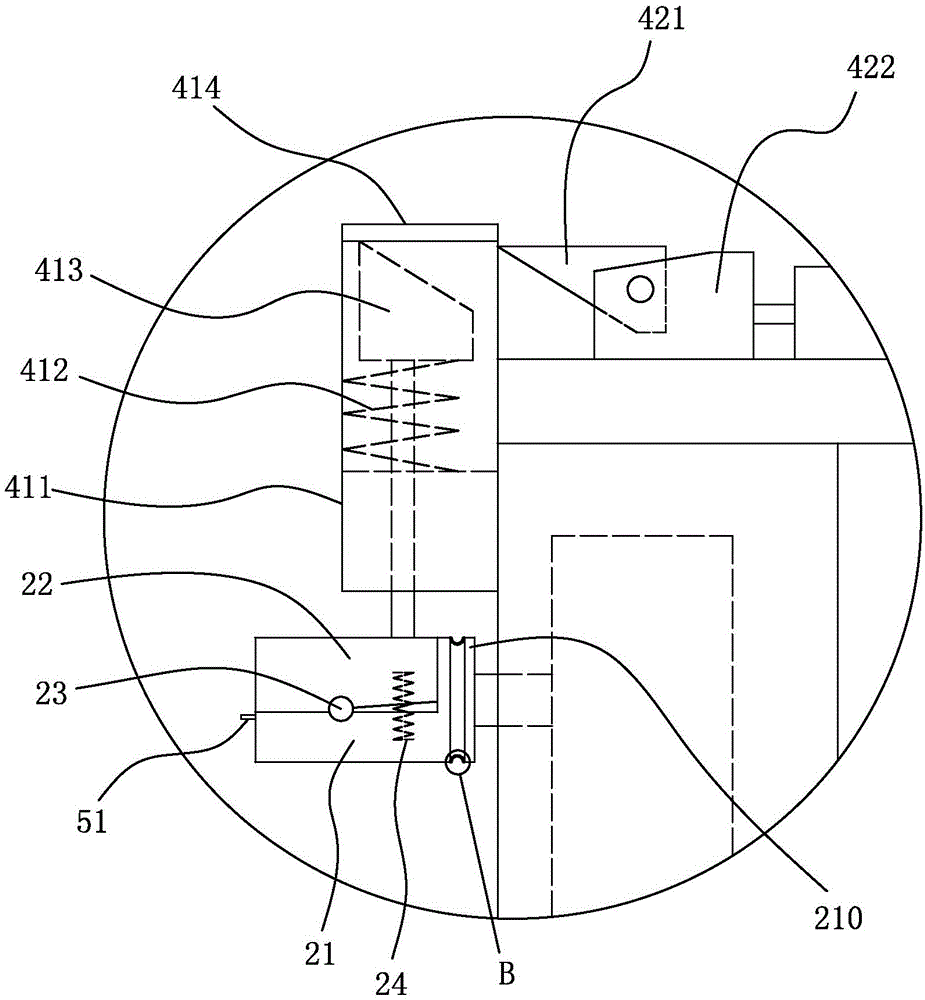
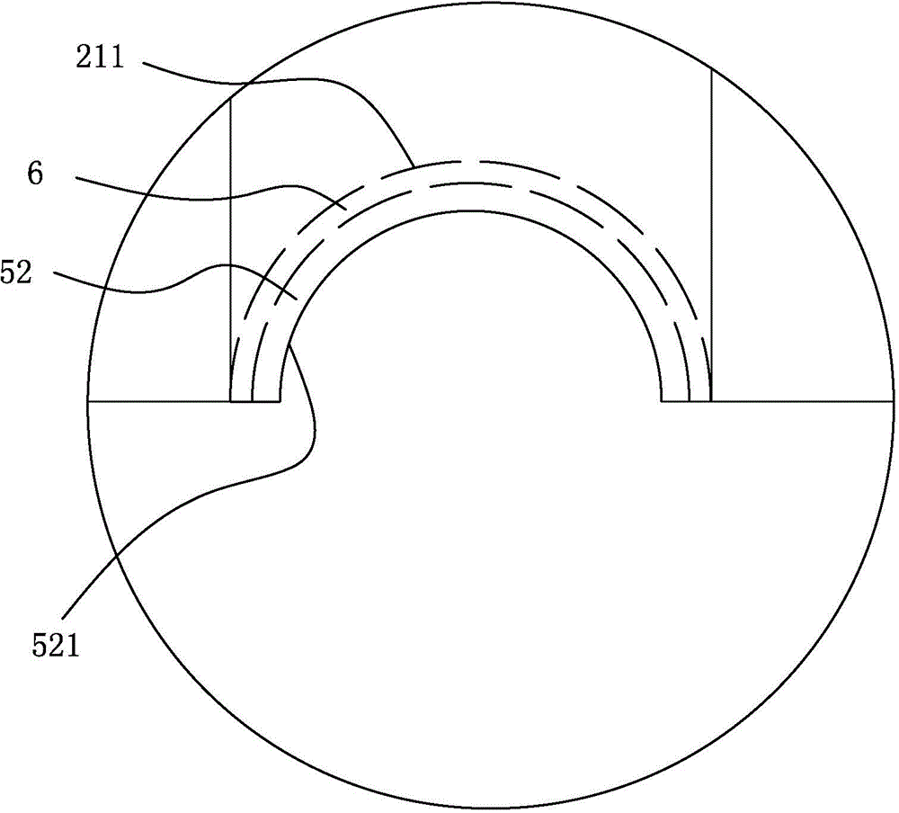
[0026] refer to Figure 1 to Figure 6 , a workpiece clamping device for a wire winding machine of the present invention includes a frame 1 and a self-relaxing clamping mechanism, and the self-releasing clamping mechanism includes a rotating mechanism arranged at both ends of the frame 1 for clamping the wire winding plate. Chuck 2, and the chuck rotation driving device that drives the rotary chuck 2 to rotate, the rotary chuck 2 includes a first clamping block 21 fixed on the frame 1, and the first clamping block 21 is hinged with a second clamping block 22 , between the first clamping block 21 and the second clamping block 22 on one side of the hinged position, there is a chuck closing elastic member 24 that drives the first clamping block 21 to close with the second clamping block 22 on the other side of the hinged position, A chuck loosening drive device 4 is arranged above the rotary chuck 2 and can apply pressure to the second chuck block 22 to compress the chuck closing ...


PUM


Abstract

The invention discloses a workpiece clamping device of a filament winder. The workpiece clamping device comprises a rack and an automatic loosening and tightening clamping mechanism. The automatic loosening and tightening clamping mechanism comprises rotating clamping heads located at the two ends of the rack and used for clamping a filament winding plate, and clamping head rotating driving devices driving the rotating clamping heads to rotate. Each rotating clamping head comprises a first clamping block fixed to the rack, wherein the first clamping block and a second clamping block are hinged, a clamping head closing elastic piece for driving the first clamping block and the second clamping block to be closed at the other side of the hinged position is arranged between the side, located at the hinged position, of the first clamping block and the second clamping block, and a clamping head loosening driving device used for exerting pressure on the second clamping block to enable the clamping head closing elastic piece to be compressed and releasing the pressure to enable the clamping head closing elastic piece to be expanded is arranged above the rotating clamping head. According to the structure, automatic loosening and tightening of the rotating clamping heads can be achieved, the loosening and tightening operation can be achieved without manual operation, time and labor are saved, and the production efficiency is high.

Description

technical field [0001] The invention relates to the field of wire winding machines, in particular to a workpiece clamping device for a wire winding machine. Background technique [0002] The electric heating plate is an indispensable part in electric heaters and electric water heaters. In the production process, a wire winding machine is generally used to wind the wire, that is, the electric heating wire is evenly wound on the insulating wire winding plate. Because the cross-section of the wire wrapping plate is rectangular, the existing wire winding machines generally use a clamping device similar to a milling machine to clamp the wire wrapping plate. During production, the clamping device needs to be manually released and clamped, which is troublesome to operate. , time-consuming and laborious, low production efficiency, and it is easy to damage the wire wrapping board due to excessive clamping force during manual clamping. [0003] In addition, in the existing wire windi...

Claims


Application Information

Patent Timeline
Patent Type & Authority Applications(China)
IPC IPC(8): B21F3/00
Inventor 何雲彬
Owner 何雲彬
Why Eureka
Try Eureka