
Pedaling type electronic accelerator pedal assembly

An electronic accelerator pedal and foot-operated technology, which is applied in the layout of the power unit control mechanism, transportation and packaging, and vehicle parts, etc., can solve the problems of inaccurate control, easy flameout when starting, etc., and achieve the effect of alleviating fatigue

Inactive Publication Date: 2015-04-22
ZHUCHENG NEW ORIENTAL AUTO METERS
View PDF0 Cites 0 Cited by
  • Summary
  • Abstract
  • Description
  • Claims
  • Application Information

AI Technical Summary

Problems solved by technology

[0002] The existing pull-wire pedals for vehicles have a simple structure and inaccurate control. If the displacement is small and the idle speed is low, it is easy to stall when starting

Method used


Image

  • Pedaling type electronic accelerator pedal assembly

Examples


Embodiment Construction

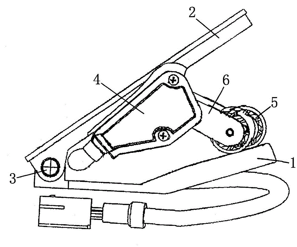
[0009] Such as figure 1 As shown, the present invention connects one end of the base 1 and one end of the pedal 2 through a rotating shaft 3, the other end of the base 1 is tilted, a sensor 4 is arranged on the bottom plane of the pedal 2, and the roller 5 is set by a bracket 6. At one corner of the sensor 4 , the roller 5 is in contact with the raised end of the base 1 . Through the above settings, when the pedal 2 of the present invention is stepped on, the roller 5 on the sensor 4 moves forward along the plane on the raised end of the base 1, and the change in the angle of the support 6 is the size of the accelerator pedal.


PUM


Abstract

The invention discloses a pedaling type electronic accelerator pedal assembly. The pedaling type electronic accelerator pedal assembly is characterized in that one end of a base is integrally connected with one end of a pedal through a rotating shaft; the other end of the base is tilted; a sensor is arranged on the plane of the bottom part of the pedal; a roller is arranged at one corner of the sensor through a bracket and is in contact fitting with an upper plane of the tilted end of the base. According to the arrangement above, the pedaling type electronic accelerator pedal assembly is used as the accelerator pedal of China fourth-generation cars, meets engineering mechanics of a human body, and is able to relieve the operation fatigue of a driver, so that the safety and reliability of use are ensured.

Description

technical field [0001] The invention relates to an electronic accelerator pedal assembly for a vehicle, to be precise, an electronic accelerator pedal assembly for a National IV automobile. Background technique [0002] The existing pull-wire pedals for vehicles have a simple structure, and the control is not accurate enough. If the displacement is small and the idle speed is low, the engine will be easily stalled when starting. Contents of the invention [0003] The object of the present invention is to provide an electronic accelerator pedal assembly for a National IV automobile. [0004] In order to achieve the above object, in the present invention, one end of the base and one end of the pedal are connected together through a rotating shaft, the other end of the base is tilted, a sensor is arranged on the bottom plane of the pedal, and a roller is arranged on a corner of the sensor through a bracket, so Said roller is in contact with the plane on the raised end of the...

Claims


Application Information

Patent Timeline
IPC IPC(8): B60K26/02
Inventor 车秀玉
Owner ZHUCHENG NEW ORIENTAL AUTO METERS
Learn More