Cable connector

A technology of cable connectors and cables, which is applied in the direction of connection, insulation cables, cables, etc., can solve the problems of loose connection between cables and inner core terminals, poor reliability of cable connectors, poor sealing of bellows and connector connections, etc. Achieve the effects of avoiding poor contact, improving reliability and sealing reliability

Active Publication Date: 2015-04-22
芜湖赛洋电气科技有限公司
View PDF10 Cites 1 Cited by
  • Summary
  • Abstract
  • Description
  • Claims
  • Application Information

AI Technical Summary

Problems solved by technology

However, this structure has the following defects: during use, the nut is easy to loosen. First, the fixing effect on the cable is lost, and the cable moves in the housing, causing the connection between the cable and the terminal in the inner core to become loose, resulting in poor contact. The cable connector on the shell is poorly sealed, and oil, water and dust are easy to enter, so the reliability of the cable connector with this structure is poor.
Another structure is that a nut threadedly connected to the port is provided at the port of the cable at one end, and a bellows is placed on the cable outside the port of the case, and a tightening piece is provided between the nut and the outer wall of the port of the bellows. Tighten the nut and fix the port of the bellows to the port of the shell. The bellows seals the cable between the port of the shell and the cable at one end, which has a certain sealing effect. In addition to the defects, there are also the following defects: one is that the cable is not fixed, and the cable will move in the housing during the movement, which will cause the connection between the cable and the terminal in the inner core to loosen, resulting in poor contact. When the joint between the bellows and the connector is poorly sealed, oil, water and dust can easily enter the cable connector and cause failures. Therefore, the reliability of the cable connector with this structure is also poor.

Method used


Image

  • Cable connector
  • Cable connector
  • Cable connector

Examples


Embodiment Construction

[0022] The present invention will be further described below according to the accompanying drawings and in conjunction with the embodiments.

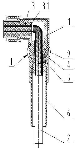
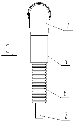
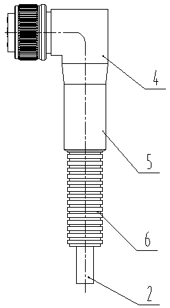
[0023] The cable connector shown in the accompanying drawings is set at one end of the cable 2 and includes a housing 1, an inner core 3, a bellows 6, an outer jacket 5, a sheath 4, and a cable tightening structure 9; the inner core 3 is set on the housing 1 In the hole; the cable 2 extends from one end of the shell 1 into the hole of the shell 1, and connects with the terminal 3.1 in the inner core 3.

[0024] Carry out the first rubber coating on the outer wall of the shell 1 part where the cable 2 extends into the shell 1, and the outer wall of the cable 2 part outside the shell 1, forming an integral structure, wrapping and sealingly connecting the cable 2 into the shell 1 Part of the outer wall of the housing 1 at the place, the sheath 4 on the outer wall of the part of the cable 2 outside the housing 1 (in other embodiments, the e...


PUM


Abstract

The invention discloses a cable connector which comprises a shell and an inner core. The inner core is arranged in a hole of the shell, and a cable extends into the hole of the shell from one end of the shell to be connected with a terminal in the inner core. Primary encapsulation is conducted on the part, which the cable extends into, of the shell, or the whole outer wall of the shell, or the part, outside the shell, of the cable, or the whole outer wall of the cable to form a sheath which is of an integrated structure and covers the part, where the cable extends into the shell, of the shell, or the whole outer wall of the shell, or the part, outside the shell, of the cable, or the whole outer wall of the cable in a seal connection mode. The cable connector is characterized in that a corrugated pipe is further arranged on the cable located outside the port of the sheath, and a jacket which is of an integrated structure, and covers the part, located at the nesting joint, of the sheath, or the whole outer wall of the sheath, or a part of the corrugated pipe or the whole outer wall of the corrugated pipe in a sealed connection mode is formed through secondary encapsulation; a cable tightening structure is further arranged on the shell; a metal lining is arranged between the cable tightening structure and the cable, and the metal lining covers a cable shielding layer. The cable connector is good in airtightness, high in reliability and long in service life.

Description

technical field [0001] The invention relates to a cable connector, in particular to a cable connector used in machine tools, industrial robots, manipulators, industrial automation equipment and the like. Background technique [0002] A large number of cable connectors are used in machine tools, industrial robots, manipulators, and industrial automation equipment. These cable connectors are set at one end of the cable, including a shell and an inner core. The inner core is set in the hole of the shell, and the cable extends from one end of the shell. In the housing hole, it is connected with the terminal in the inner core. When these cable connectors are used normally, they are required to have high reliability in use. The cable connectors in the prior art have two main structures. One structure is that a nut threadedly connected with the port is provided at the housing port where the cable extends into one end, and a cone is provided between the inner hole of the housing an...

Claims


Application Information

Patent Timeline
Patent Type & Authority Applications(China)
IPC IPC(8): H01R13/52H01B7/17H01R13/405
CPCH01R13/5205H01R13/56H01R13/58
Inventor 颜国兵
Owner 芜湖赛洋电气科技有限公司
Why Eureka
Try Eureka