AC solid state relay and fault detecting method of load circuit of same

A solid-state relay and power circuit technology, applied in circuit breaker testing, electrical components, electronic switches, etc., can solve the problem that the reliability and safety of solid-state relays cannot be guaranteed, increase the complexity of internal circuits and design and manufacturing costs, and cannot detect Solid-state relay thyristor failure and other problems, to increase the complexity of the circuit, the overall structure is compact and compact, and improve the safety and reliability of use

Active Publication Date: 2015-02-04
许蓬
View PDF11 Cites 25 Cited by
  • Summary
  • Abstract
  • Description
  • Claims
  • Application Information

AI Technical Summary

Problems solved by technology

However, the above-mentioned detection method cannot be used to make the solid-state relay into a standard conventional size, and the volume and size need to be enlarged or specially customized, which makes the overall circuit structure bulky, and at the same time increases the complexity of the internal circuit and the design and manufacturing cost; In addition, using the above-mentioned The detection method is generally unable to detect the thyristor failure inside the solid state relay itself, and cannot guarantee the reliability and safety of the solid state relay

Method used


Image

  • AC solid state relay and fault detecting method of load circuit of same
  • AC solid state relay and fault detecting method of load circuit of same
  • AC solid state relay and fault detecting method of load circuit of same

Examples


Embodiment Construction

[0042] The present invention will be further described in detail below in conjunction with the accompanying drawings and embodiments.

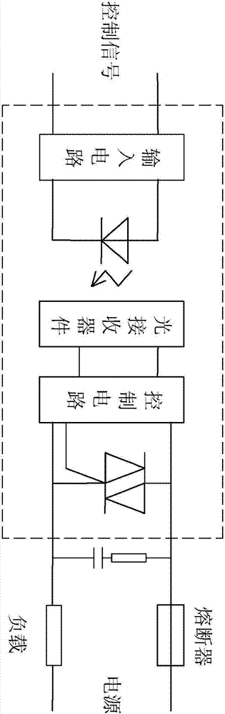
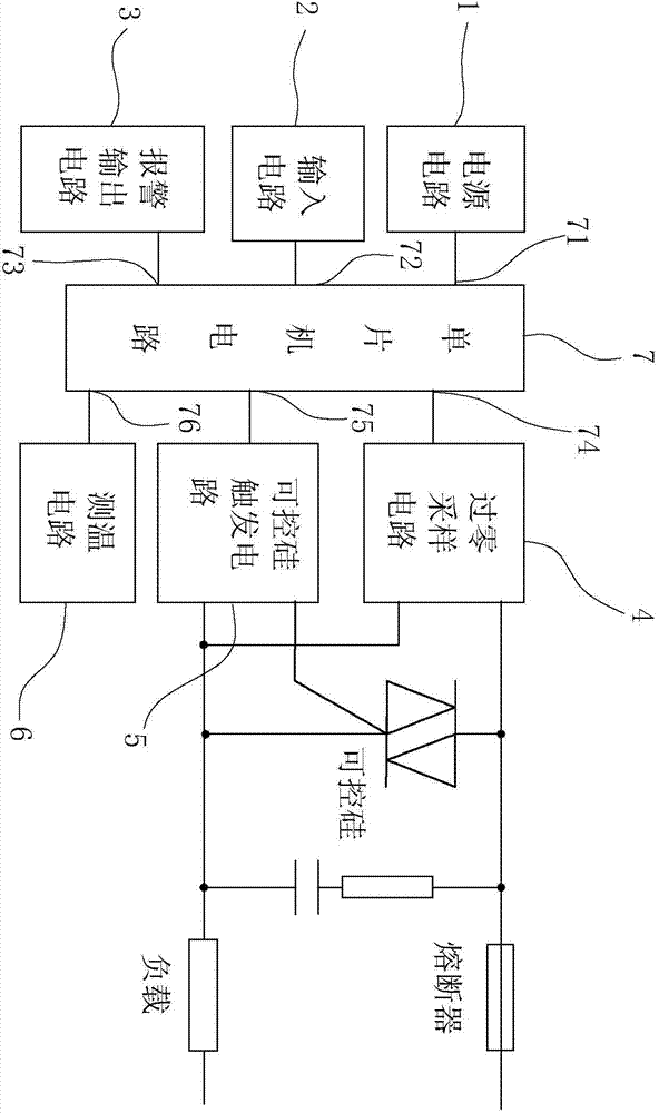
[0043] Such as Figure 2 to Figure 9 As shown, the present invention discloses an AC solid state relay and its internal circuit connection structure. The AC solid state relay includes a power supply circuit 1, an input circuit 2, a thyristor, an alarm output circuit 3, a zero-crossing sampling circuit 4, a controllable Silicon trigger circuit 5, temperature measuring circuit 6 and single-chip microcomputer 7, single-chip microcomputer 7 includes power input terminal 71, signal input terminal 72, alarm output terminal 73, zero-crossing signal detection terminal 74, trigger signal output terminal 75 and temperature detection terminal 76, see figure 2 ;

[0044] Wherein, the function of the power supply circuit 1 is to convert the external power supply into the power supply required by the internal circuit, and the output terminal of the power...


PUM


Abstract

The invention provides an AC solid state relay. The AC solid state relay comprises a power circuit, an input circuit, controllable silicon and an alarm output circuit. The AC solid state relay is characterized by further comprising a single-chip microcomputer; the output end of the power circuit is connected with the power input end of the single-chip microcomputer; the output end of the input circuit is connected with the signal input end of the single-chip microcomputer; the alarm output end of the single-chip microcomputer is connected with the input end of the alarm output circuit; the sampling ends of a zero-passage sampling circuit are respectively connected in parallel to two ends of the controllable silicon; the zero passage signal output end is connected with the zero passage signal detecting end of the single-chip microcomputer; the control input end of a controllable silicon triggering circuit is connected with the triggering signal output end of the single-chip microcomputer; the first control output end is connected with the control end of the controllable silicon; the second control output end is connected with an cathode or an anode of the controllable silicon. The AC solid state relay has the advantages that the mode of obtaining the zero passage signal by direct connecting in parallel to the controllable silicon is adopted, thus the fault detection of a load circuit is realized on the premise that the complexity of the circuit is not increased; in addition, the fault of the open circuit in the controllable silicon can also be detected; the control is performed through the single-chip microcomputer, so that the intelligent solid state relay is realized, and the safety and reliability and the product are improved.

Description

technical field [0001] The invention relates to an AC solid state relay and a fault detection method for a load circuit (including relay fault and load fault) of the AC solid state relay. Background technique [0002] Solid state relay (SSR for short) is a commonly used control executive device in industrial automation control. It is a non-contact switch composed of microelectronic circuits, discrete electronic devices and power electronic power devices. The isolation device realizes the isolation between the control terminal and the load terminal. . Conventional AC solid state relay internal circuit such as figure 1 The dotted line box shown generally consists of three parts: input circuit, isolation (coupling) circuit and output circuit, wherein the output circuit is composed of switching elements (such as unidirectional thyristor, bidirectional thyristor, etc.) and control circuit. [0003] In the application of electrical automatic control, where the safety and reliabi...

Claims


Application Information

Patent Timeline
Patent Type & Authority Applications(China)
IPC IPC(8): H03K17/785G01R31/327
Inventor 许蓬
Owner 许蓬
Why Eureka
Try Eureka