Electrical switch forming a fast actuation circuit breaker

An electrical switch and conductive sheet technology, applied to the following types of electrical switches and electrical switches that function as circuit breakers, can solve problems such as difficulty in installing sliding components

Active Publication Date: 2015-04-22
ARIANEGRP SAS
View PDF4 Cites 9 Cited by
  • Summary
  • Abstract
  • Description
  • Claims
  • Application Information

AI Technical Summary

Problems solved by technology

It thus proves to be difficult to mount the slide assembly

Method used


Image

  • Electrical switch forming a fast actuation circuit breaker
  • Electrical switch forming a fast actuation circuit breaker
  • Electrical switch forming a fast actuation circuit breaker

Examples


Embodiment Construction

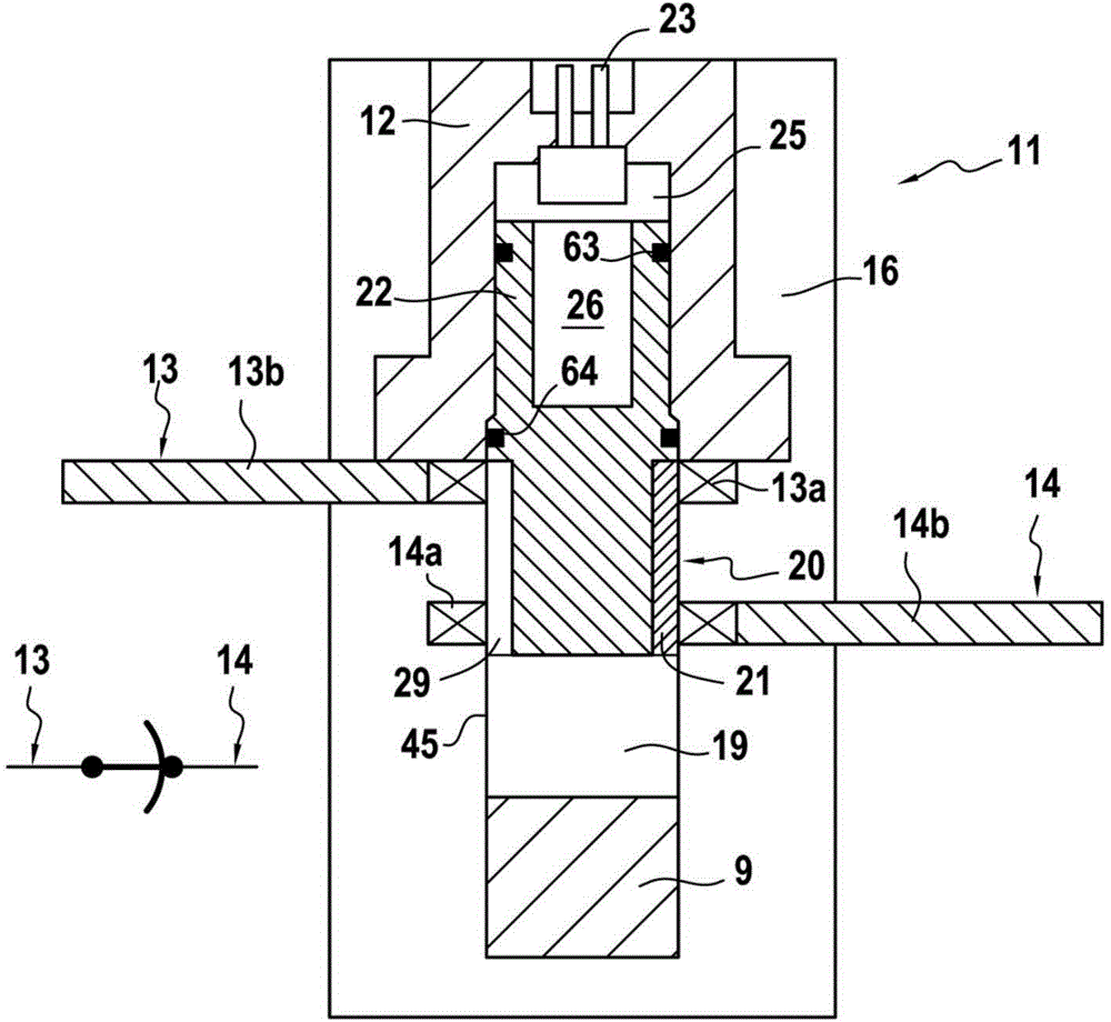
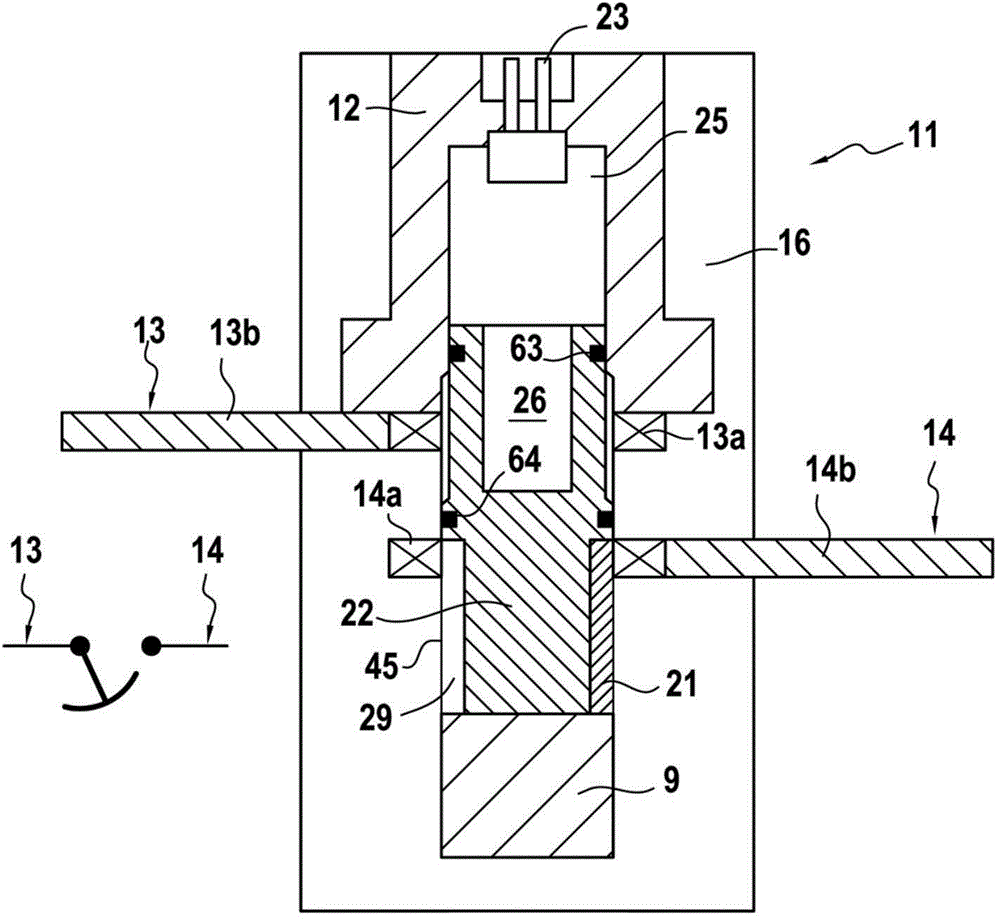
[0045] Referring more specifically to Figure 1 and figure 2 , it is possible to see a first embodiment of the electric switch 11 according to the invention, in this example the electric switch 11 more particularly constitutes a circuit breaker for any electric circuit connected to the two primary conductive strips 13 and 14 as defined above .

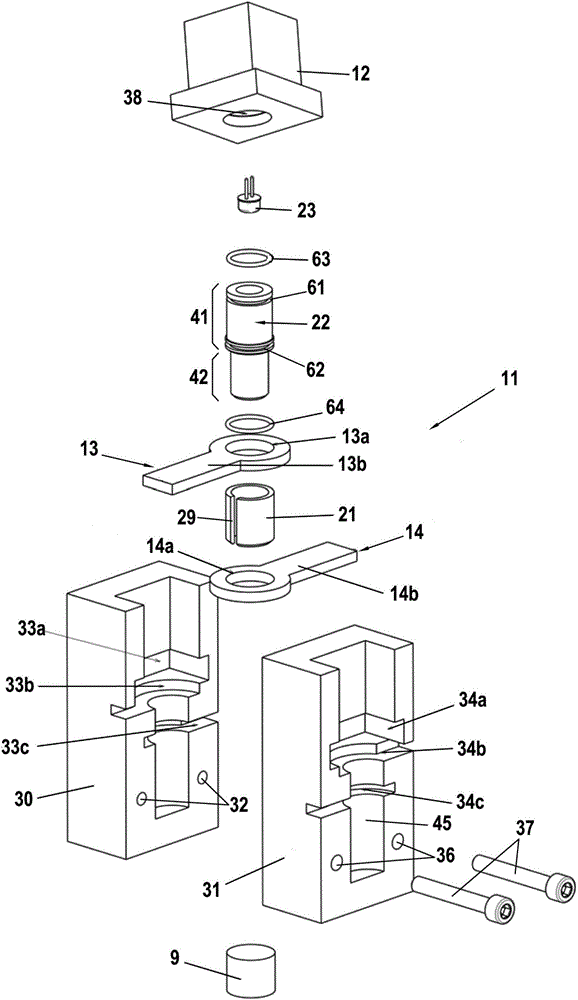
[0046] The circuit breaker switch 11 has a hollow body 16 of electrically insulating material defining a cavity 19 , an actuator 23 and two primary conductive strips 13 , 14 protruding into the cavity 19 .

[0047] The electric switch 11 also has a sliding assembly 20 adapted to move in the cavity. In the example shown, cavity 19 is cylindrical and slide assembly 20 itself is substantially cylindrical.

[0048] The slide assembly 20 includes a split tube 21 having at least one conductive portion. In Figure 1 and figure 2 In the example shown, the open tube 21 is electrically conductive as a whole.

[0049] The sliding assembly 20...


PUM


Abstract

A normally closed electrical switch having a sliding assembly actuated on opening, for example by a pyrotechnic gas generator. Prior to actuation, a conductive portion of the sliding assembly (21) is in tight contact with two axially offset coaxial rings (13a, 14a) belonging respectively to two electrically conductive pads (13, 14), and after the actuator is triggered, the upstream pad (13) is released from the conductive portion of the sliding assembly. According to the invention, the sliding assembly comprises a tube provided with a slot extending along the entire length of same, and the conductive portion of the sliding assembly consists of all or a portion of said slotted tube, the clamping force between the conductive portion and the primary electrically conductive pads being provided by the elasticity of the slotted tube.

Description

technical field [0001] The invention relates in particular to electrical switches functioning as circuit breakers. More particularly, the present invention relates to an electrical switch having a slide assembly, in particular an electrical switch of the type comprising: a hollow body defining a cavity; a slide assembly including at least one conductive portion and adapted to move within the cavity from an "initial" first position to a second position; an actuator arranged to cooperate with the slide assembly and cause the slide assembly to move in the moving in said cavity; and at least two primary conductive sheets respectively being upstream conductive sheets and downstream conductive sheets, both conductive sheets comprising rings protruding into said cavities, said rings being coaxial and at said The moving direction of the sliding assembly is axially offset, wherein, when the sliding assembly is at the first position, the conductive part of the sliding assembly is in cl...

Claims


Application Information

Patent Timeline
IPC IPC(8): H01H39/00
CPCH01H39/004H01H1/365H01H1/06H01H39/00
Inventor 弗雷德里克·马林罗曼·罗伦宗
Owner ARIANEGRP SAS
Why Eureka
Try Eureka