Shoe cabinet with drying function

A shoe cabinet and functional technology, applied in the field of shoe cabinets, can solve problems such as inconvenience and inability to put in the shoe cabinet, and achieve the effect of removing moisture

Inactive Publication Date: 2015-04-29
陈潇
View PDF0 Cites 2 Cited by
  • Summary
  • Abstract
  • Description
  • Claims
  • Application Information

AI Technical Summary

Problems solved by technology

[0002] Most of the existing shoe cabinets only have the function of storing shoes. When the rainy day comes, the wet shoes can only be piled outside the door and cannot be put into the shoe cabinet, which is very inconvenient

Method used


Image

  • Shoe cabinet with drying function

Examples


Embodiment Construction

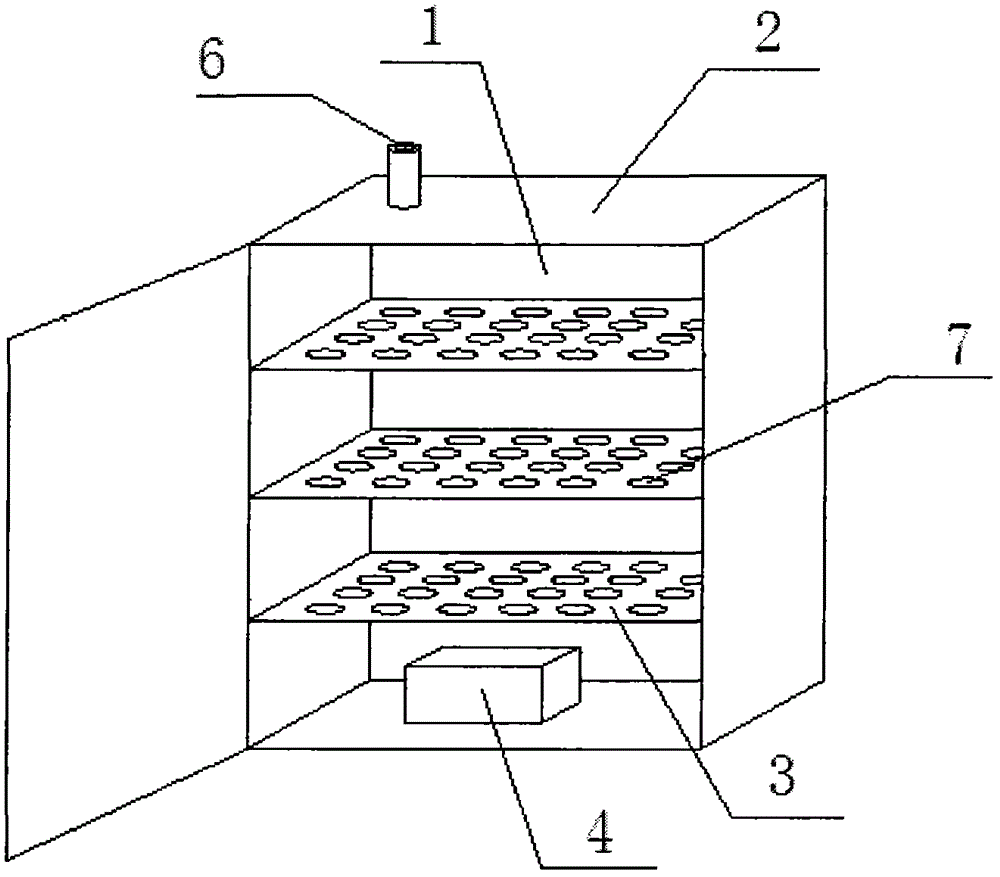
[0010] refer to figure 1 The shown shoe cabinet with drying function includes a cabinet main body 2 with a cavity 1, a partition 3 arranged in the cavity 1, and a dehumidifier 4 provided at the bottom of the cavity 1. The cabinet The top of the main body 2 is provided with an exhaust pipe 6 communicating with the cavity 1 .

[0011] Wherein, the partition board 3 is provided with more than one piece, and the partition board 3 is provided with a ventilation hole 7 .

[0012] The beneficial effects of the present invention are: through the dehumidifier at the bottom of the cavity, the moisture in the shoes can be effectively removed, so that the shoes can be dried quickly, and the moisture can be discharged from the main body of the cabinet through the exhaust pipe.

[0013] The above is only a specific implementation of the present invention, but the scope of protection of the present invention is not limited thereto, and any changes or replacements that do not come to mind th...


PUM


Abstract

The invention discloses a shoe cabinet with a drying function. The shoe cabinet comprises a cabinet body with a cavity, partition plates and a dehumidifier, the partition plates are arranged in the cavity, the dehumidifier is arranged at the bottom of the cavity, and an exhaust pipe communicated with the cavity is arranged at the top of the cabinet body. By the aid of the dehumidifier at the bottom of the cavity, moisture in shoes can be removed effectively to enable the shoes to be dried quickly; by the aid of the exhaust pipe, moisture can be discharged outside the cabinet body.

Description

technical field [0001] The invention relates to a shoe cabinet with drying function. Background technique [0002] Most of the existing shoe cabinets only have the function of storing shoes. When the rainy day comes, the wet shoes can only be piled outside the door and cannot be put into the shoe cabinet, which is very inconvenient. Contents of the invention [0003] The technical problem to be solved by the present invention is to provide a shoe cabinet with a drying function that can quickly dry shoes. [0004] In order to solve the above problems, the present invention adopts the following technical solutions: [0005] A shoe cabinet with a drying function, comprising a cabinet main body with a cavity, a partition arranged in the cavity, and a dehumidifier provided at the bottom of the cavity, and a drain connected to the cavity is arranged on the top of the cabinet main body. trachea. [0006] Preferably, more than one partition is provided, and ventilation holes ar...

Claims


Application Information

Patent Timeline
Patent Type & Authority Applications(China)
IPC IPC(8): A47B61/04A47B96/02
CPCA47B61/04A47B96/02A47B2220/00
Inventor 陈潇
Owner 陈潇
Why Eureka
Try Eureka