Camera Module for Vehicle

a technology for vehicles and cameras, applied in cameras, television systems, instruments, etc., can solve problems such as difficulty for the driver or passenger of the vehicle to s

Active Publication Date: 2016-07-21
LG INNOTEK CO LTD
View PDF7 Cites 23 Cited by
  • Summary
  • Abstract
  • Description
  • Claims
  • Application Information

AI Technical Summary

Benefits of technology

[0010]In one embodiment, a camera module includes a lens unit, a coupling unit coupled to the lens unit, a housing coupled to the coupling unit, the housing being configured to accommodate a printed circuit b...

Problems solved by technology

In addition, camera modules are increasingly being used as recognition devices to clearly and easily...

Method used


Image

  • Camera Module for Vehicle
  • Camera Module for Vehicle
  • Camera Module for Vehicle

Examples


Embodiment Construction

[0025]Hereinafter, embodiments will be described with reference to the annexed drawings. In the drawings, the same or similar elements are denoted by the same reference numerals even though they are depicted in different drawings. In the following description, a detailed description of known functions and configurations incorporated herein will be omitted when it may make the subject matter of the disclosure rather unclear. Those skilled in the art will appreciate that some features in the drawings are exaggerated, reduced, or simplified for ease in description, and drawings and elements thereof are not shown always at the proper rate.

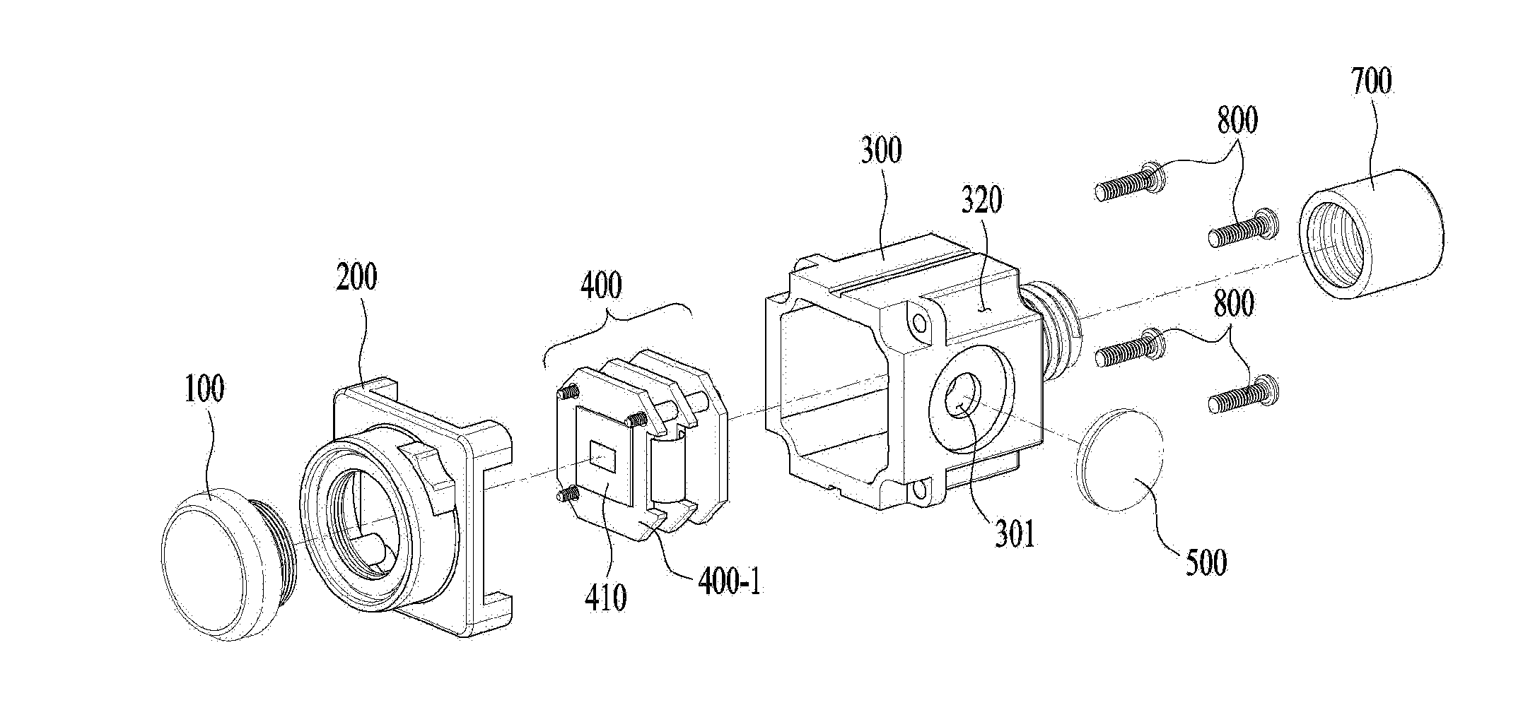
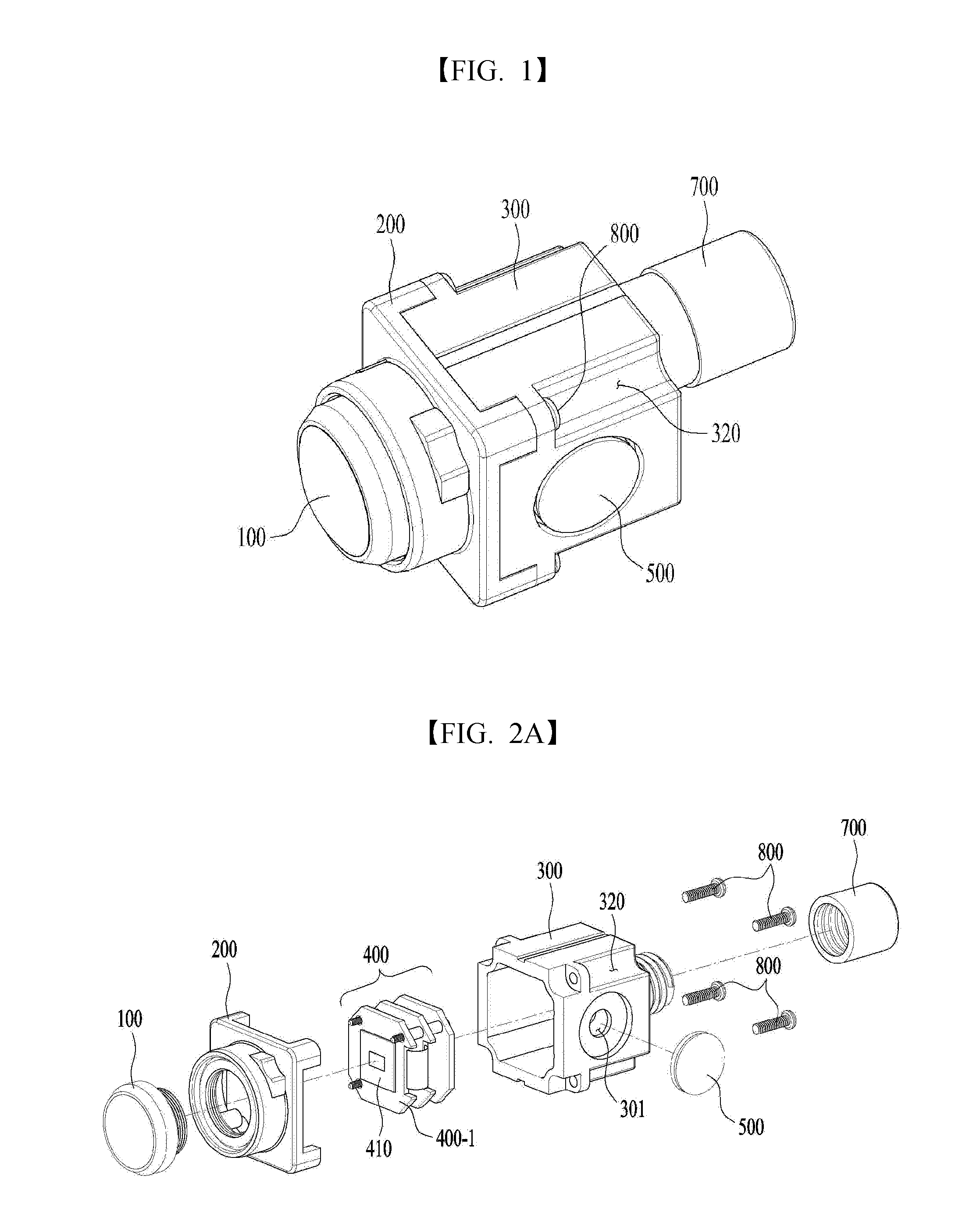
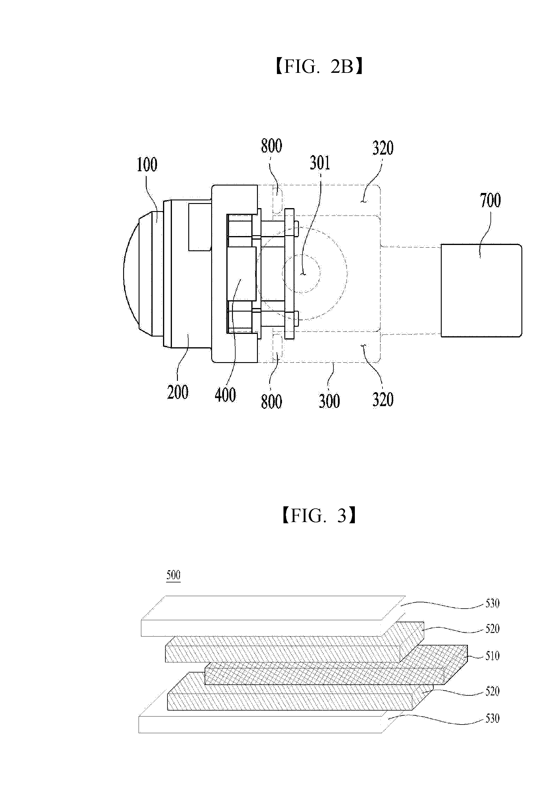
[0026]FIG. 1 is a perspective view illustrating a camera module in accordance with one embodiment. FIG. 2A is an exploded perspective view illustrating the camera module in accordance with one embodiment. FIG. 2B is a view illustrating the configuration of the camera module in accordance with one embodiment.

[0027]The camera module in accordance with on...


PUM


Abstract

Embodiments provide a camera module including a lens unit, a coupling unit coupled to the lens unit, a housing coupled to the coupling unit, the housing being configured to accommodate a printed circuit board therein and having a vent formed therein, and a membrane formed of an air-permeable material and configured to close the vent formed in the housing so as to prevent external foreign substances from entering the housing.

Description

CROSS REFERENCE TO RELATED APPLICATION[0001]This application claims priority under 35 U.S.C. §119 to Korean Patent Application No. 10-2015-0007359, filed Jan. 15, 2015, which is hereby incorporated by reference in its entirety.TECHNICAL FIELD[0002]Embodiments relate to a camera module for a vehicle.BACKGROUND[0003]Content described herein merely provides background information related to embodiments and does not constitute the related art.[0004]Camera modules having various use purposes may be mounted to vehicles. For example, a camera module that is capable of providing rearward vision while a vehicle is being parked, may be mounted to the rear portion of the vehicle.[0005]In addition, camera modules may also be used in black boxes for vehicles, which have recently become very useful to clarify, for example, the details of an accident and the cause of the accident when a traffic accident occurs. In addition, camera modules are increasingly being used as recognition devices to clear...

Claims


Application Information

Patent Timeline
IPC IPC(8): H04N5/225G06K9/00H04N7/18
CPCH04N5/2252G06K9/00791H04N5/2254H04N7/185H04N23/51H04N23/55G03B17/02G03B17/08H04N23/57G03B17/55G03B30/00G06V20/56
Inventor AHN, JAE WOOKPARK, JE KYUNGHWANG, SUN MIN
Owner LG INNOTEK CO LTD
Why Eureka
Try Eureka