Room temperature heat exchanger for breathing circuit

Active Publication Date: 2007-03-08
GENERAL ELECTRIC CO
View PDF2 Cites 20 Cited by
  • Summary
  • Abstract
  • Description
  • Claims
  • Application Information

AI Technical Summary

Benefits of technology

[0013] The heat exchanger positioned within the breathing circuit removes water vapor and reduces the temperature of the breathing gases prior to the breathing gases contacting various se

Problems solved by technology

However, the CO2 absorber in such a circuit creates an exothermic reaction that heats the breathing gas and entrains additional water vapor into the breathing gas.
As the breathing of the patient continues, the condensed

Method used


Image

  • Room temperature heat exchanger for breathing circuit
  • Room temperature heat exchanger for breathing circuit
  • Room temperature heat exchanger for breathing circuit

Examples


Example

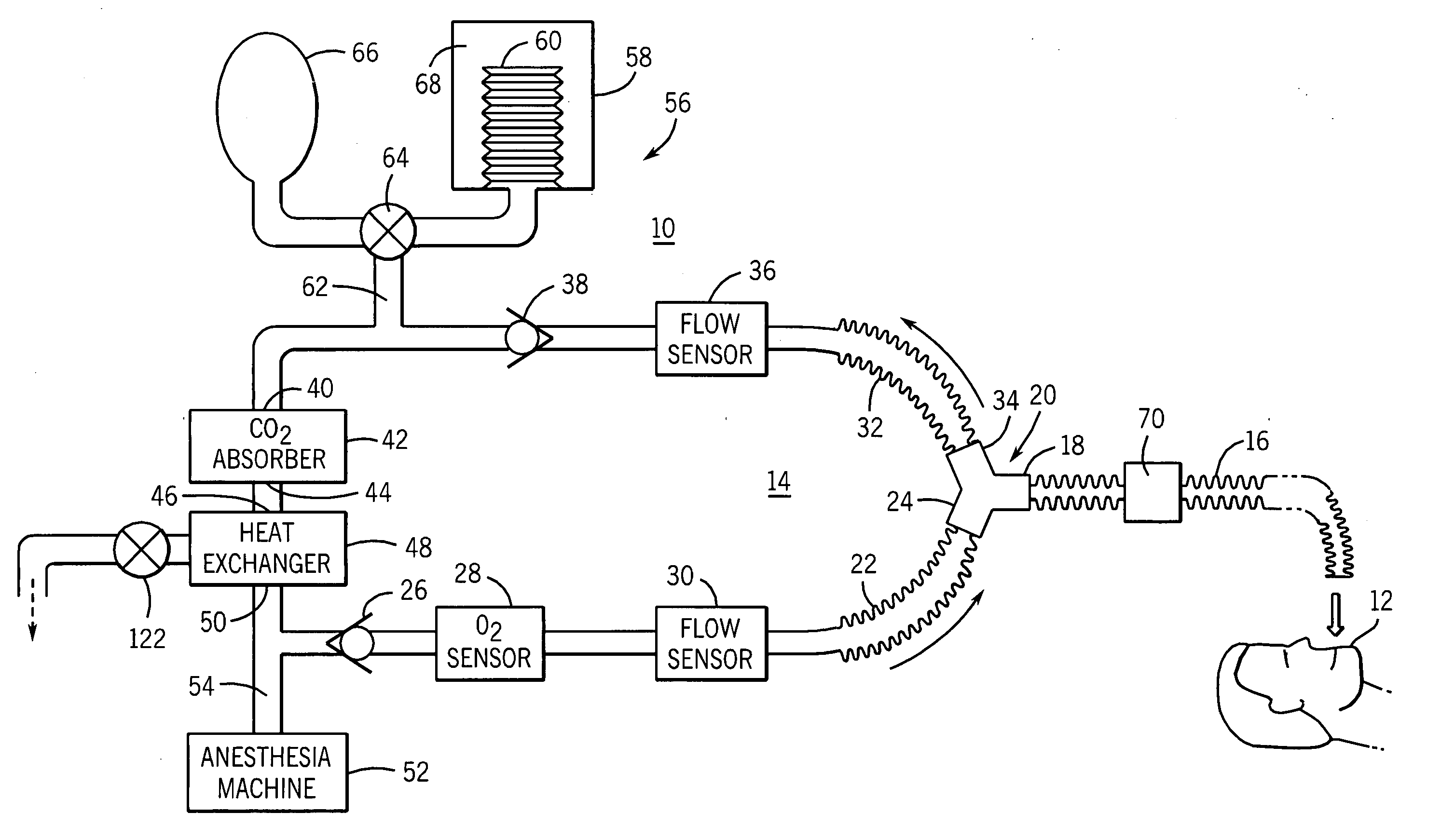
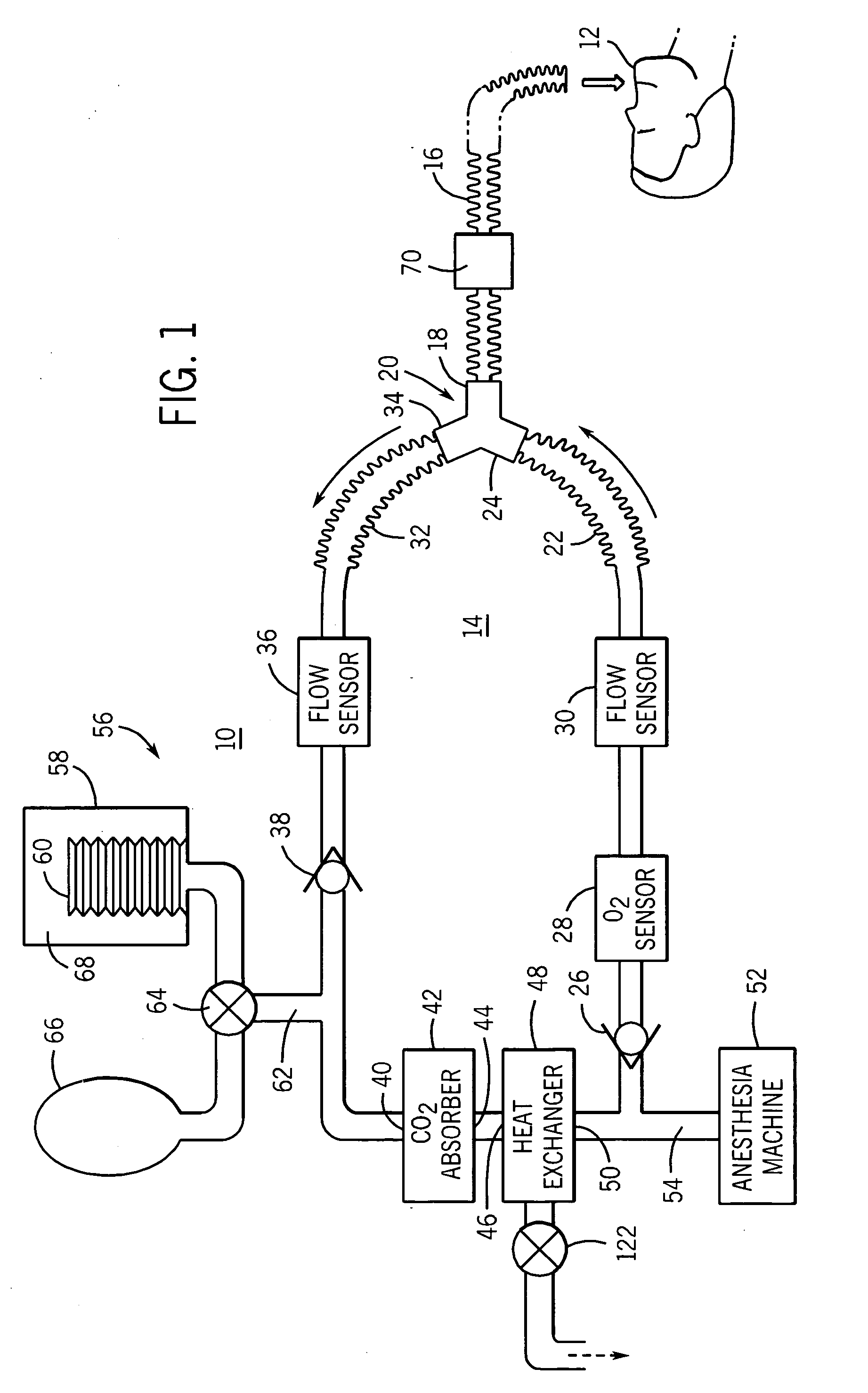
[0019]FIG. 1 illustrates a ventilation system 10 for mechanically ventilating a patient 12. The ventilation system 10 includes a closed breathing circuit 14. The closed breathing circuit 14 includes a patient limb 16 that delivers breathing gases to the patient 12 from a first leg 18 of a Y-connector 20.

[0020] The breathing circuit 14 includes an inspiration limb 22 connected to the inlet leg 24 of the Y-connector 20. The inspiration limb 22 receives the flow of breathing gases to be supplied to the patient 12 through a check valve 26. In the embodiment of the invention illustrated, an oxygen sensor 28 and a flow sensor 30 are positioned between the check valve 26 and the inspiration limb 22.

[0021] The closed breathing circuit 14 includes an expiration limb 32 connected to the outlet leg 34 of the Y-connector 20 to receive the exhaled breathing gases from the patient. The exhaled breathing gases pass through a flow sensor 36 and a check valve 38. The expiration limb 32 is connecte...


PUM


Abstract

A breathing circuit for use with a ventilated patient that includes a heat exchanger for removing water vapor from the breathing gases to prevent condensation within the breathing circuit. The heat exchanger is positioned downstream from the CO2 absorber and receives the breathing gases from the CO2 absorber prior to delivery of the breathing gases to the inspiration limb of the patient circuit. The heat exchanger includes a plurality of inflow tubes and outflow tubes that are each open to a sump removably attached to the heat exchanger. The sump collects the water vapor condensed from the breathing gases within the heat exchanger.

Description

BACKGROUND OF THE INVENTION [0001] The present invention generally relates to a breathing circuit having a device for removing entrained water vapor from the breathing gas within the breathing circuit. More specifically, the present invention relates to a heat exchanger positioned within the breathing circuit to reduce the condensation at other areas within the breathing circuit. [0002] A mechanical ventilator is often used to supply and remove breathing gases from a patient. The operation of the ventilator may be to assist and / or replace the natural breathing action of the patient, either alone or with the supply of an anesthetic agent to the patient. A typical mechanical ventilator has an inspiration limb for supplying breathing gases to the patient and an expiration limb for receiving breathing gases from the patient. The inspiration and expiration limbs are connected to arms of a Y-connector. A patient limb extends from a third arm of the Y-connector to an intubation tube or fac...

Claims


Application Information

Patent Timeline
IPC IPC(8): A61M15/00
CPCA61M16/1045A61M2016/0042A61M2016/0039A61M16/22A61M16/1055Y10S128/911A61M16/106A61M2016/1025A61M16/0833A61M16/0808
Inventor MASHAK, JAMES N.INMAN, SCOTT A.PERNETTI, DENISE L.THAM, ROBERT Q.
Owner GENERAL ELECTRIC CO
Why Eureka
Try Eureka