Printer, and paper position detection method of a printer

一种检测方法、打印机的技术,应用在打印装置、印刷等方向,能够解决装置制造成本增加、难以实现装置小型化等问题

Inactive Publication Date: 2015-04-29
SEIKO EPSON CORP
View PDF7 Cites 2 Cited by
  • Summary
  • Abstract
  • Description
  • Claims
  • Application Information

AI Technical Summary

Problems solved by technology

[0008] Mounting a fan and a filter for capturing ink mist on a printer requires space to arrange them, making it difficult to downsize the device
In addition, a driving source for driving the fan is required, and there is a problem that the manufacturing cost of the device increases.

Method used


Image

  • Printer, and paper position detection method of a printer
  • Printer, and paper position detection method of a printer
  • Printer, and paper position detection method of a printer

Examples


no. 1 approach

[0042] Hereinafter, an embodiment of a printer 1 to which the present invention is applied will be described with reference to the drawings.

[0043] (the whole frame)

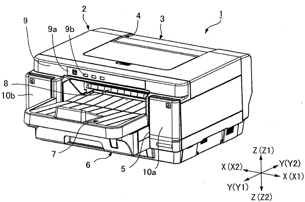
[0044] figure 1 It is an external perspective view of the printer 1 according to the first embodiment viewed from the direction of the paper discharge port 8 (referred to as the front). The printer 1 has a printer main body 2 and a reversing unit 3 . The printer main body 2 has a rectangular parallelepiped shape that is long in the printer width direction X as a whole. The reversing unit 3 is mounted to a recess 4 provided at a central portion of the rear surface of the printer main body portion 2 . The reversing unit 3 is a unit for reversing the printing paper P from the front to the back.

[0045] A paper feeding cassette mounting portion 5 is provided on the printer main body portion 2 . The paper feeding cassette mounting portion 5 opens toward the printer front Y1 (forward in the printer longitudina...

no. 2 approach

[0113] Next, refer to Figure 1 ~ Figure 4 as well as Figure 12 to Figure 17 Another embodiment of the printer 1 to which the present invention is applied will be described.

[0114] Figure 12 It is a perspective view of the carriage in which the print head 12 is mounted in the second embodiment viewed from below. Figure 13 (a), (b) are perspective views when the carriage 45 in the state which removed the paper detector cover 73 was seen from below. Figure 13 (a) shows the state where the shutter 185 is arranged at the closed position 185A, Figure 13 (b) shows the state where the shutter 185 is arrange|positioned at the open position 185B. Figure 14 It is an explanatory diagram of the shutter 185 and the shutter operating member 210 . Figure 15 It is a perspective view when the carriage 45 moved to the initial position B is seen from above. Figure 16 It is a perspective view of the carriage 45 when it moves to the shutter open position D (described later) seen fr...

no. 3 approach

[0156] Next, refer to Figure 1 ~ Figure 4 as well as Figure 19 ~ Figure 22 Another embodiment of the printer 1 to which the present invention is applied will be described.

[0157] Figure 19 It is a perspective view of the carriage in which the print head 12 is mounted in the third embodiment viewed from below. Figure 20 (a), (b) are perspective views when the carriage 45 in the state which removed the paper detector cover 73 was seen from below. Figure 20 (a) shows the state where the shutter 285 is arranged at the closed position 285A, Figure 20 (b) shows the state where the shutter 285 is arrange|positioned at the open position 285B. Figure 21 It is an explanatory diagram of the shutter 285 and the shutter moving mechanism 290 . Figure 22 It is a flowchart of the opening and closing operation of the shutter and the paper position detection operation. It should be noted that, in Figure 19 ~ Figure 22In the description, the same reference numerals are assigned...


PUM


Abstract

Airborne ink mist is prevented from sticking to the detector part of a paper detector disposed on a carriage without using a configuration for capturing the ink mist. A printer has a conveyance path that conveys paper past the print position of a printhead; a carriage that carries the printhead; and a carriage moving mechanism that moves the carriage bidirectionally on the transverse axis of the printer. A paper detector and a shutter that opens and closes the detection part of the paper detector are disposed on the carriage. When the carriage moves to one end of the range of carriage movement, a shutter operating member disposed on a second side frame facing the carriage contacts the shutter and moves the shutter from its open position or closed position to the other position.

Description

technical field [0001] The present invention relates to a printer having a paper detector mounted on a carriage and a paper position detection method of the printer. Background technique [0002] In the serial printer, the printing paper is conveyed along a conveyance path passing the printing position of the printing head, and the planned printing start position on the printing paper is positioned as the printing position. Thereafter, the printing operation and the paper feeding operation are repeated and alternately performed. The printing operation is an operation of printing while moving the printing head along the width direction of the conveying path perpendicular to the conveying direction of the printing paper at the printing position, The paper feeding operation is an operation of feeding printing paper by a predetermined paper feeding amount at a time along the feeding path. The print head is mounted on a carriage, and the carriage reciprocates in the width direct...

Claims


Application Information

Patent Timeline
Patent Type & Authority Applications(China)
IPC IPC(8): B41J2/01B41J11/00
CPCB41J11/0095
Inventor 有贺勇一矢部宏
Owner SEIKO EPSON CORP
Why Eureka
Try Eureka