Vibrating Conveyor

A conveying device and vibrating technology, which is applied in the field of vibrating conveying devices, can solve problems such as difficult adjustment of vibration number, inability to obtain sufficient performance, inability to obtain sufficient amplitude, etc.

Active Publication Date: 2017-04-12
DAISHIN CO LTD
View PDF9 Cites 0 Cited by
  • Summary
  • Abstract
  • Description
  • Claims
  • Application Information

AI Technical Summary

Problems solved by technology

However, when the size of conveyed objects such as electronic devices becomes smaller, other devices arranged in front and rear positions in the conveying direction of the production line are also reduced in size, so the conveying device is also required to be miniaturized.
However, on the other hand, in order to suppress the overall height of the device, it is considered to shorten the length of the leaf spring. However, when the length of the leaf spring is shortened, there is a problem that it cannot be obtained on the conveyance path due to the relationship of the spring constant. Sufficient amplitude, or difficulty in adjusting the number of vibrations, resulting in insufficient performance

Method used


Image

  • Vibrating Conveyor
  • Vibrating Conveyor
  • Vibrating Conveyor

Examples


Embodiment Construction

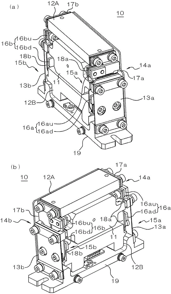
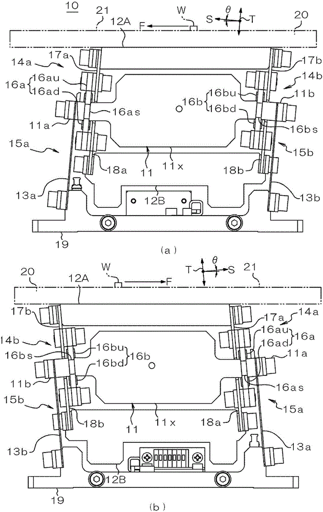
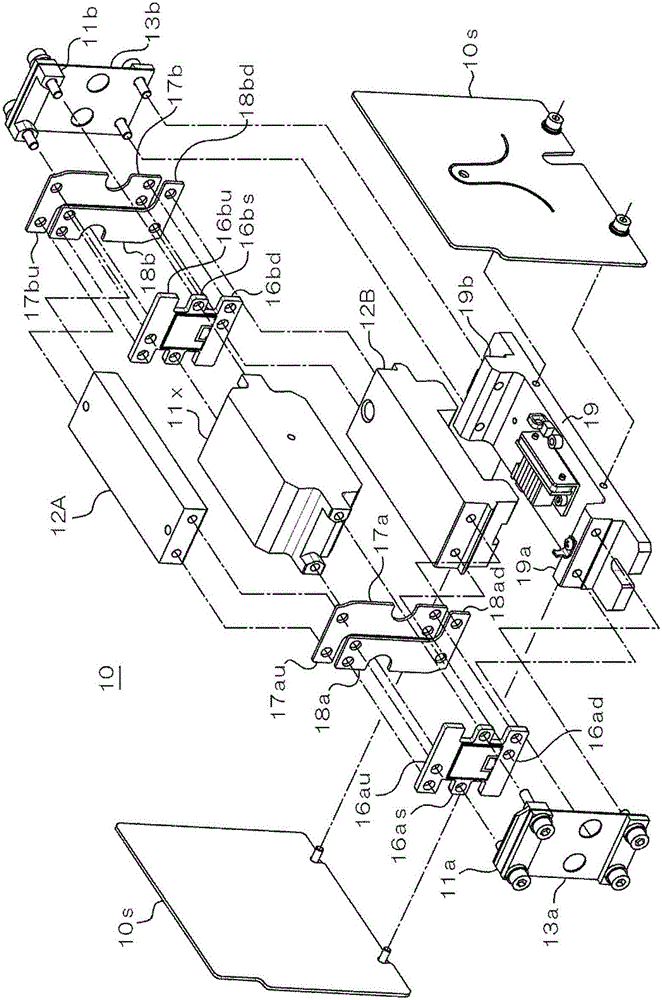
[0052] Next, embodiments of the present invention will be described in detail with reference to the drawings. Figure 1 ~ Figure 3 These are a perspective view, a side view, and an exploded perspective view showing the overall structure of the present embodiment, respectively. in addition, Figure 4 is the front view of the piezoelectric actuator, Figure 5 It is a front view showing the up and down amplifying springs connected to the upper mass body and the lower mass body.

[0053] The vibratory conveying device 10 of the present embodiment includes a reference mass body 11 , an upper mass body 12A disposed above the reference mass body 11 , and a lower mass body 12B disposed below the reference mass body 11 . The reference mass body 11 is moving along the conveying direction F (refer to figure 2 ) in the conveying direction are respectively supported from below by plate-shaped anti-vibration springs 13a and 13b, wherein the plate-shaped anti-vibration springs 13a and 13...


PUM


Abstract

The invention provides a vibratory conveying apparatus capable of obtaining a stable conveying state and ensuring conveying performance while the apparatus is minimized. The vibratory conveying apparatus (10) is provided with a reference mass body (11) supported by a pair of vibration-proof springs (13a, 13b), an upper-side mass body (12B) arranged above the reference mass body and a lower-side mass body (12B) arranged below the reference mass body, upper-portion vibration springs (14a, 14b) enabling the reference mass body to be elastically connected with the upper-side mass body, lower-portion vibration springs (15a, 15b) enabling the reference mass body to be elastically connected with the lower-side mass body, and in-phase excitation mechanisms (16a, 16b)arranged between the reference mass body and the lower-side mass body and used for producing in-phase vibration in the conveying direction. The upper-portion vibration springs are provided with lower-side protruding portions (16ad, 12bd) used for upper-portion vibration and with upper-side elastic portions (17a, 17b) used for upper-portion vibration. The lower-portion vibration springs are provided with upper-side protruding portions (16au, 16 bu) used for lower-portion vibration and lower-side elastic portions (18a, 18b) used for lower-portion vibration.

Description

technical field [0001] The present invention relates to a vibrating conveying device, and particularly relates to a conveying mechanism of a conveying device suitable for conveying components in a straight line. Background technique [0002] Usually, the vibrating conveying device is configured such that the conveying body is elastically supported on a base via a leaf spring, and the conveying body is excited by a vibrating mechanism such as an electromagnetic driver or a piezoelectric driver to produce an oblique upward movement toward the conveying direction. Vibration, thereby conveying objects such as parts along the conveying path formed on the conveying body. In recent years, since the use of tiny electronic devices as transport objects has increased, and the demand for high-speed supply of such tiny transport objects has become increasingly high, it is therefore necessary to use a piezoelectric drive source to vibrate in large numbers, so that the tiny transport objec...

Claims


Application Information

Patent Timeline
Patent Type & Authority Patents(China)
IPC IPC(8): B65G27/28
Inventor 原顺一木内勇希
Owner DAISHIN CO LTD
Why Eureka
Try Eureka