Stamping and feeding device of high-grade steel

A feeding equipment and material clamping technology, applied in the field of workpiece processing, can solve the problems that the material cannot be accurately punched in the preset position, the material is prone to deflection, and the material is damaged, so as to improve the stability, reduce the path, and improve the success rate. Effect

Inactive Publication Date: 2019-02-22
HANGZHOU KINGNET ELECTROMECHANICAL
View PDF5 Cites 0 Cited by
  • Summary
  • Abstract
  • Description
  • Claims
  • Application Information

AI Technical Summary

Problems solved by technology

[0003] When feeding steel, the material is previously pushed along the upper end of the equipment, and the material is prone to deflection during the pushing process, which leads to the fact that the punch cannot accurately punch the material at the preset position during the stamping process. As a result, only half of the material that could have been punched out of the complete product was punched due to the deflection of the material, causing the material to be damaged and unusable, and the punched product is also an invalid product

Method used


Image

  • Stamping and feeding device of high-grade steel
  • Stamping and feeding device of high-grade steel
  • Stamping and feeding device of high-grade steel

Examples


Embodiment Construction

[0034] In order to enable those skilled in the art to better understand the solutions of the present invention, the technical solutions in the embodiments of the present invention will be clearly and completely described below in conjunction with the drawings in the embodiments of the present invention.

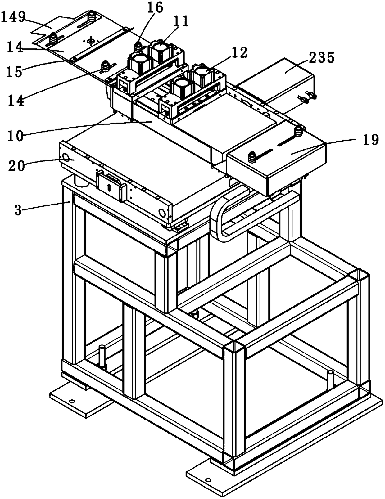
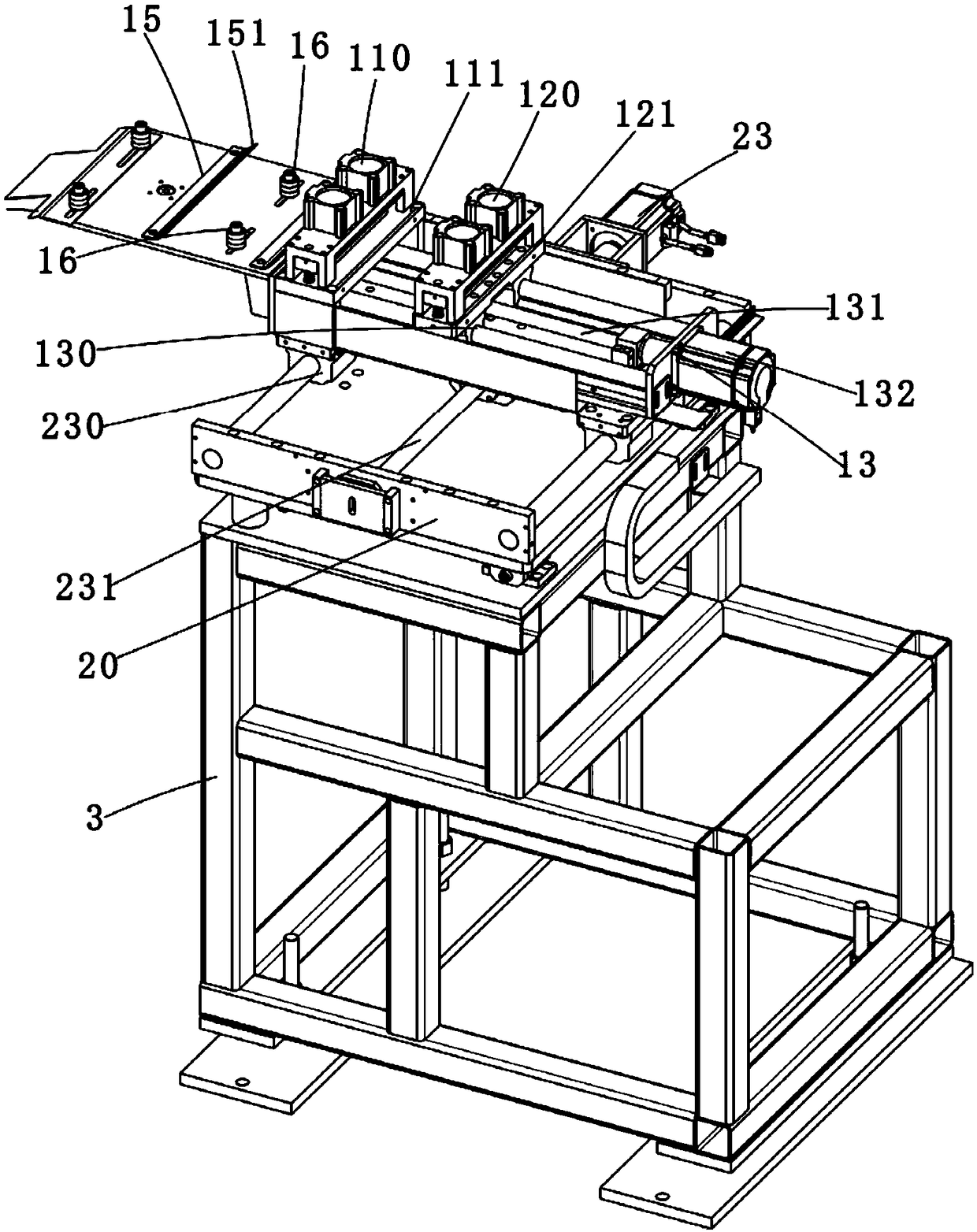
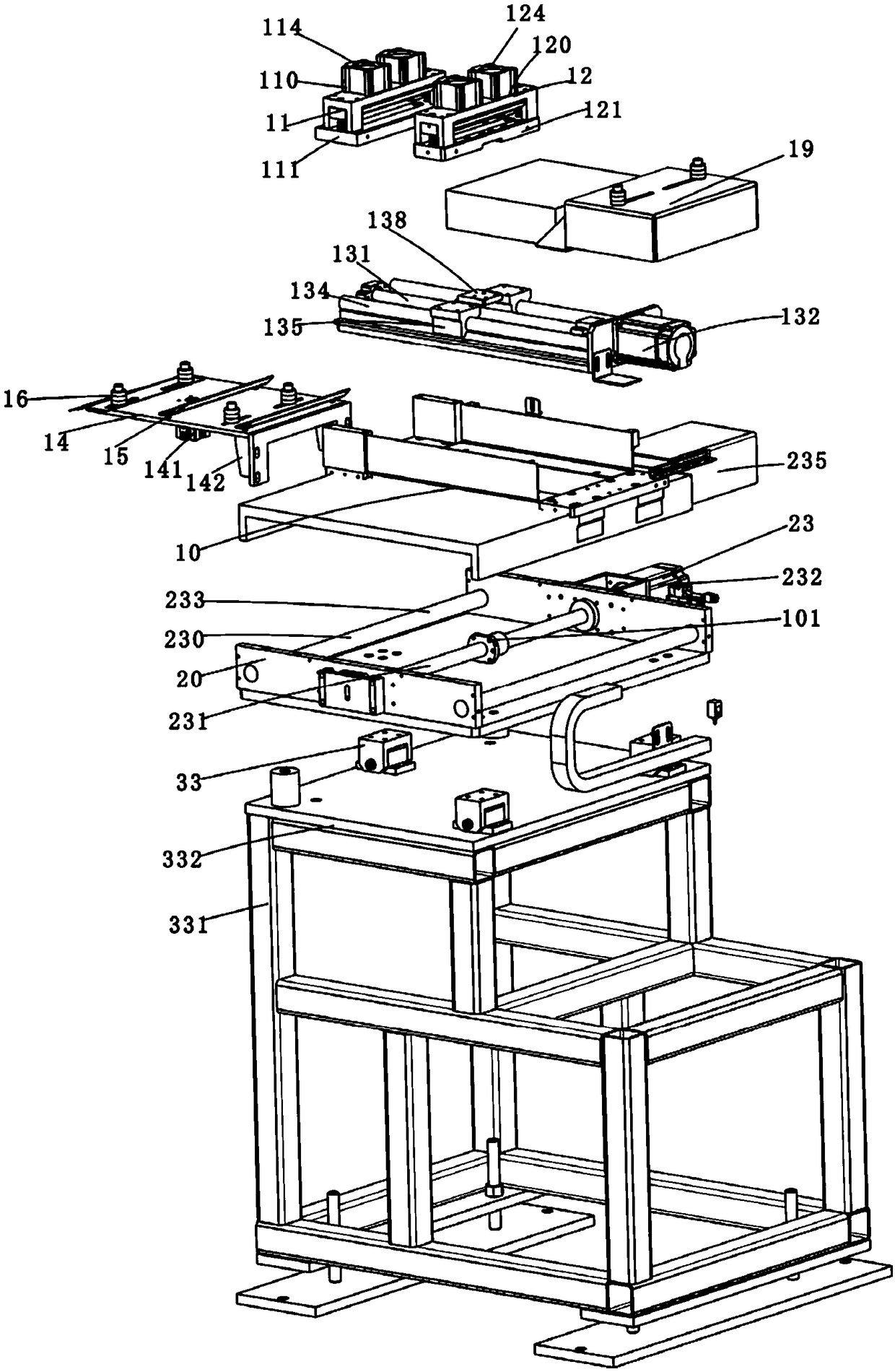
[0035] Such as Figure 1-14 As shown, a high-quality steel stamping feeding equipment includes a first frame body 10, a first clamping device 11, a second clamping device 12 and a first driving device 13, wherein the first clamping device 11 and the second The material clamping devices 12 are all arranged on the first frame body 10, and the first material clamping device 11 and the second material clamping device 12 cooperate with each other to feed materials when feeding. The specific cooperation is: the initial material is manually or otherwise When the equipment is fed into the entire side feeder, the second clamping device 12 first clamps the material, and then pushes the...


PUM


Abstract

The invention discloses a stamping and feeding device of high-grade steel. The stamping and feeding device of the high-grade steel comprises a first frame body, a first material clamping device, a second material clamping device and a limiting device, wherein the first material clamping device is arranged on the first frame body and is used for clamping materials; the second material clamping device cooperates with the first material clamping device, when the first material clamping device clamps the materials, the second material clamping device moves backwards, and then when the materials are loosened by the first material clamping device, the second clamping device is used for clamping the materials to move forwards; the limiting device is used for limiting the materials so as to keep the materials linearly moving from the back to the front. According to the device, by arranging the limiting device, the materials can be limited when the materials are conveyed so that the whole materials can move linearly in one direction all the time, the success rate of the whole stamped material can be improved, the material waste can be reduced, and the qualified rate of products can be improved.

Description

technical field [0001] The invention belongs to the technical field of workpiece processing, and in particular relates to high-quality steel stamping and feeding equipment. Background technique [0002] At present, in my country's iron and steel industry, the steel produced can be roughly divided into ordinary steel and high-quality steel according to the carbon content in the steel. General steel is a large steel that is common in our daily life, such as steel used in construction materials. Frames, etc., while high-quality steel has the advantages of low carbon content, high hardness, and light weight. It is mostly used for blades, chains, etc.; currently, the high-quality steel produced by steel mills is limited due to the process, and the general width of high-quality steel is limited to 350mm. Inside, its width is relatively narrow. During the use of high-quality steel, it punches high-quality steel through punching equipment. The stamping process is to press the punch to...

Claims


Application Information

Patent Timeline
Patent Type & Authority Applications(China)
IPC IPC(8): B21D43/02B21D43/00F16F15/08B30B15/04
Inventor 胡志华
Owner HANGZHOU KINGNET ELECTROMECHANICAL
Why Eureka
Try Eureka