Tissue ablation device and method of use

Inactive Publication Date: 2005-02-15
RGT UNIV OF CALIFORNIA
View PDF300 Cites 106 Cited by
  • Summary
  • Abstract
  • Description
  • Claims
  • Application Information

AI Technical Summary

Benefits of technology

Described by the Cox procedure, as referenced above, is a strategy to incur patterned surgical incisions within the atrial chambers, creating a maze by which propagating electrical waves are extinguished at the lines of suture. In this way, reentrant wavelets are not sustained, arrhythmia cannot persist, and normal sinus rhythm is restored. Curative efforts for atrial arrhythmias were initially focused on the right atrium, with mixed results. However, procedures which combine right and left atrial treatments have been observed to have d

Problems solved by technology

The resulting loss of blood flow due to incomplete cardiac contractions along with a rapid heart rate can lead to shortness of breath, dizziness, limited physical endurance, and chest pains.
Persistence of atrial fibrillation renders an individual susceptible to congestive heart failure, stroke, other thromboembolic events, and myocardial ischemia.
Numerous cardiac arrhythmias, such as atrial fibrillation, were once thought untreatable except by pharmacological or surgical intervention, both capable of manifesting undesirable side effects.
However, the administration of such medications sometimes does not restore normal cardiac hemodynamics, and may ultimately exacerbate the arrhythmic condition through the occurrence of proarrhythmia.
However, such focal lesions are not appropriate for most cases of

Method used


Image

  • Tissue ablation device and method of use
  • Tissue ablation device and method of use
  • Tissue ablation device and method of use

Examples


Example

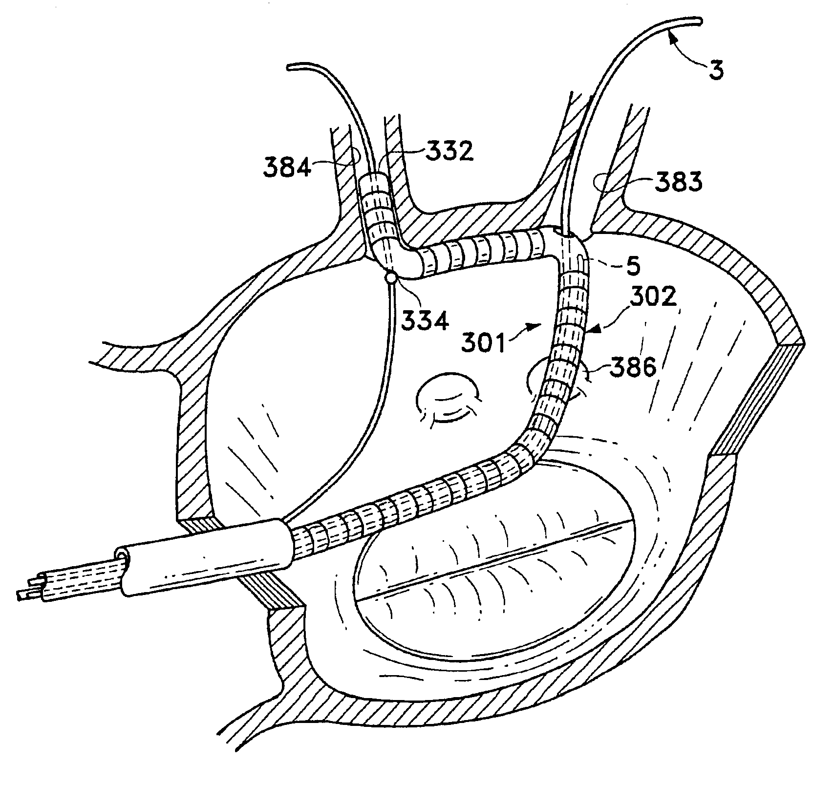
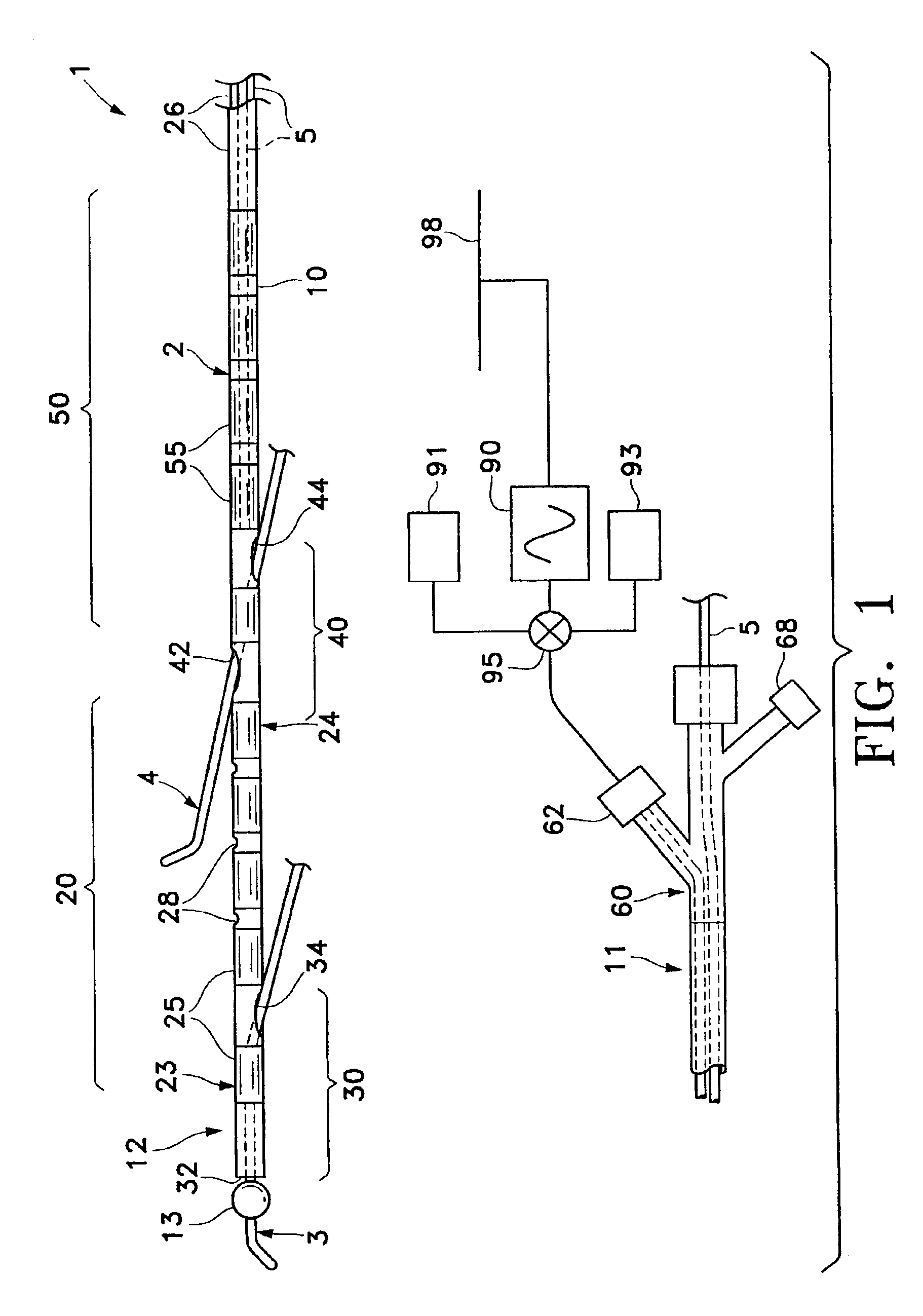
The present invention is herein described by reference to particularly desirable embodiments shown in the figures. However, the present invention broadly provides an elongate ablation element with anchors at multiple regions of that element, such as at each of its ends, which allow those ends to be secured at predetermined locations along a body space wall, such as along an atrial wall. In this novel arrangement, the ablation element is adapted to firmly contact a continuous length of tissue along the body space wall between the predetermined locations to form a long linear lesion in that tissue.

The term “anchor” is herein intended to mean an element which is at least in part located in an anchoring region of the device and which is adapted to secure that region at a predetermined location along a body space wall. As such, “anchor” is intended to provide fixation as a securing means over and above a mere normal force against a single tissue surface which is created by confronting co...


PUM


Abstract

A tissue ablation device creates long linear lesions along a body space wall of an animal, and primarily between adjacent pulmonary vein ostia in a left atrial wall. An ablation element includes first and second ends that are bordered by first and second anchors. The anchors are adapted to secure the ablation element ends at predetermined first and second locations along the body space wall such that the ablation element is adapted to ablate an elongate region of tissue between those locations. The anchors may be guidewire tracking members, each including a bore adapted to receive and track over a guidewire, and may anchor within adjacent pulmonary vein ostia when the engaged guidewires are positioned within the respective veins. Stop members may be provided on the guidewires and may be adapted for positioning the relative anchors or for forcing the anchors to fit snugly within the vein ostia. A conduit passageway through the catheter houses a stiffening stylet which may be advanced into the region of the ablation element in order to impart a shape to that element to conform it to a predetermined region of anatomy, or to stiffen the underlying catheter in order to advance the assembly into remote anatomy.

Description

STATEMENT REGARDING FEDERALLY SPONSORED RESEARCH OR DEVELOPMENTNot ApplicableREFERENCE TO A COMPUTER PROGRAM APPENDIXNot ApplicableBACKGROUND OF THE INVENTION1. Field of the InventionThe present invention is a surgical device. More particularly, it is a medical catheter assembly that has an ablation element which is adapted to have its two ends anchored at predetermined locations on a body space wall such that the ablation element is adapted to firmly contact the length of tissue between predetermined locations for the purpose of forming a long linear lesion therebetween.2. Description of the Background ArtAtrial FibrillationCardiac arrhythmias, and atrial fibrillation in particular, remain a persistent medical condition in modern society. In the United States alone, approximately 1% of the total adult population is afflicted by atrial fibrillation, currently more than 2.5 million people, with prevalence increasing as a function of age. The resulting loss of blood flow due to incomp...

Claims


Application Information

Patent Timeline
IPC IPC(8): A61B18/14A61B17/22A61B17/00A61B18/12
CPCA61B18/1492A61B2218/002A61B2017/00243A61B2017/22038A61B2017/22054A61B2017/22067A61B2018/00011A61B2018/0016A61B2018/00214A61B2018/00273A61B2018/00285A61B2018/00291A61B2018/00369A61B2018/00375A61B2018/00797A61B2018/00815A61B2018/00821A61B2018/00839A61B2018/00898A61B2018/00994A61B18/1815
Inventor LESH, MICHAEL D.
Owner RGT UNIV OF CALIFORNIA
Why Eureka
Try Eureka