Landscape wind wells and buildings

A wind shaft and landscape technology, applied in the direction of architecture, building components, building structures, etc., can solve the problems of destroying the facade style, destroying the sight line of outdoor buildings, occupying space, etc.

Active Publication Date: 2017-01-18
SHENZHEN GENERAL INST OF ARCHITECTURAL DESIGN & RES
View PDF4 Cites 2 Cited by
  • Summary
  • Abstract
  • Description
  • Claims
  • Application Information

AI Technical Summary

Problems solved by technology

[0004] The main disadvantages of these ventilation shafts protruding from the ground are: 1. Destroying the facade style, occupying the lighting and ventilation surface of the building's outer wall; 2. Occupying limited outdoor space, affecting outdoor use; 3. Destroying outdoor buildings (especially It is the line of sight of those all-glass curtain wall buildings with higher requirements) and outdoor landscape

Method used


Image

  • Landscape wind wells and buildings
  • Landscape wind wells and buildings
  • Landscape wind wells and buildings

Examples


Embodiment 1

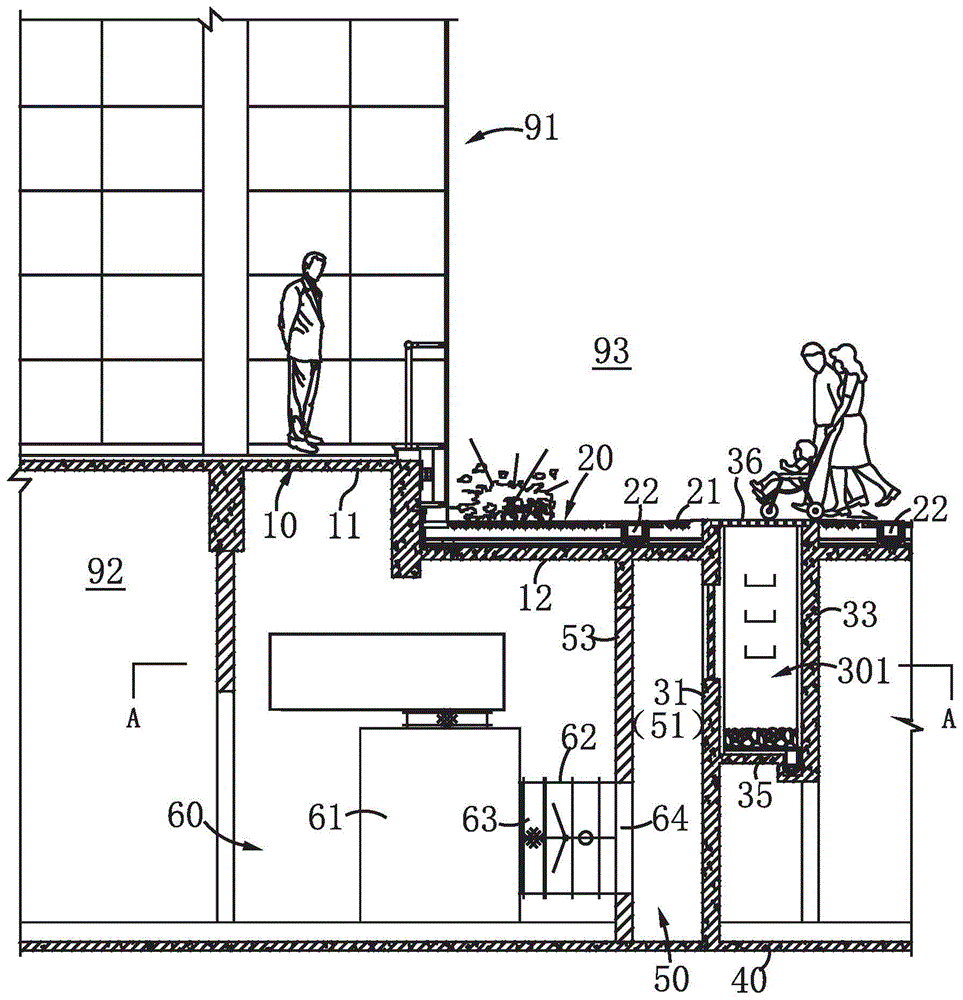
[0022] This embodiment provides a building equipped with a landscape wind shaft. Such as figure 1 , figure 2 As shown, the building includes an above-ground building body 91 and a basement 92 . Wherein, the roof 10 of the basement includes a first roof part 11 located below the main body of the above-ground building and a second roof part 12 located at the outer periphery of the main body of the above-ground building, that is to say, the second roof part 12 refers to that the basement roof 10 exceeds the building facade other parts. The second roof part 12 is laid with an outdoor floor layer 20, which can be used as a road, a square or a green area.

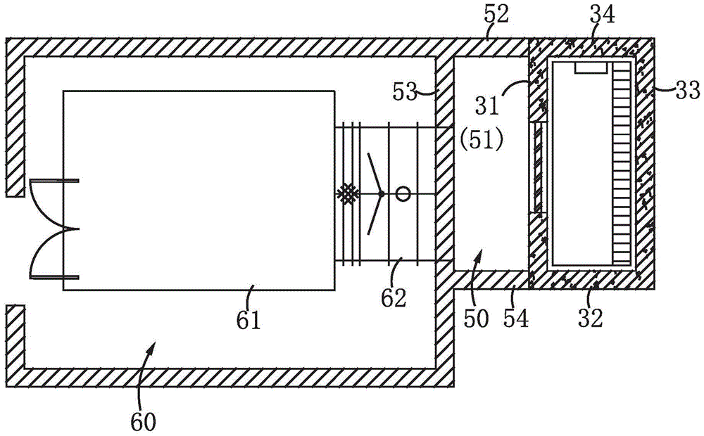
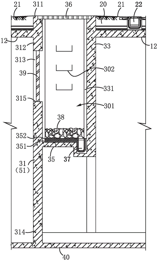
[0023] The building of this embodiment also includes a landscape wind shaft 30, which is arranged below the second roof part 12, and is mainly composed of four side walls 31, 32, 33, 34, a bottom plate 35 and a cover plate 36 , wherein the four side walls are respectively the left side wall 31, the lower side wall 32, the r...

Embodiment 2

[0031] This embodiment provides a landscape air shaft. The structure of the landscape air shaft is substantially the same as the structure of the landscape air shaft described in the above embodiments, so details will not be repeated here.


PUM


Abstract

The invention relates to the field of buildings, in particular to a landscape air shaft and a building. The landscape air shaft is communicated with a basement of the building and an external space of the building and comprises a plurality of side walls, a bottom plate and a cover plate. The side walls and the bottom plate are arranged below an outdoor grade level of the building to form an air shaft cavity with the top open, the opening is communicated with an upper space of the outdoor grade level, and at least one of the side walls is provided with a ventilation port communicated with the basement. The cover plate is arranged at the opening of the air shaft and approximately flushes with the outdoor grade level of the building, and a grating cover plate or a metal grating plate serves as the cover plate. Due to the fact that an air outlet of the landscape air shaft is integrated with the indoor grade level to form a uniform landscape, damages and occupancy of building facades or external landscapes due to protrusion of a traditional air shaft protruding out of the earth's surface are avoided, and more activity spaces can be created for people to have various social activities.

Description

technical field [0001] The invention relates to the field of architecture, in particular to a landscape wind well and architecture. Background technique [0002] With the improvement of economic and technological level, the basement design of urban buildings is becoming more and more complicated and the scale is getting bigger and bigger. For example, underground garages, equipment rooms, and civil air defense projects, these underground buildings must be well designed for air supply and exhaust, and each fire compartment must have at least two ventilation shafts that can lead to the outside. Therefore, every basement must have several to a dozen ventilation shafts, and dozens or even hundreds of ventilation shafts. Therefore, how to reasonably plan and set the position of the air shaft on the ground has become one of the difficulties in the design of basement buildings. [0003] For these basement-to-outdoor air shafts, see Figure 4 , the conventional design method is to...

Claims


Application Information

Patent Timeline
Patent Type & Authority Patents(China)
IPC IPC(8): E04F17/04
Inventor 郑宛君
Owner SHENZHEN GENERAL INST OF ARCHITECTURAL DESIGN & RES
Why Eureka
Try Eureka