
An automatic door lock locking out control mechanism

A technology of automatic door lock and control mechanism, which is applied in the direction of building lock, building structure, construction, etc. to achieve the effect of flexible arrangement

Active Publication Date: 2017-01-25
WONLY SECURITY & PROTECTION TECH CO LTD
View PDF2 Cites 0 Cited by
  • Summary
  • Abstract
  • Description
  • Claims
  • Application Information

AI Technical Summary

Problems solved by technology

[0006] For this reason, the technical problem to be solved by the present invention is that in the prior art, it is impossible to achieve reliable locking and sensitive locking after the lock tongue is retracted while the lock-out control mechanism is flexibly arranged. To provide a flexible arrangement, Reliable locking, automatic door lock lock-out control mechanism that can be locked sensitively

Method used


Image

  • An automatic door lock locking out control mechanism
  • An automatic door lock locking out control mechanism
  • An automatic door lock locking out control mechanism

Examples


Embodiment Construction

[0045] In the following, the present invention will be further described by using the following embodiments in conjunction with the accompanying drawings.

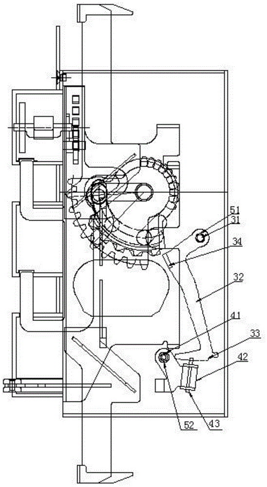
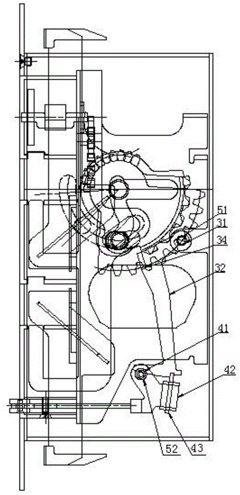
[0046] Such as Figure 1-2 As shown, the automatic door lock unlocking control mechanism of the present invention includes a deadbolt member installed in the cavity of the lock case, and a trigger assembly arranged in the housing space of the lock case or the deadbolt. A locking assembly for locking or unlocking the locking tongue member, a pusher arranged on the locking tongue member and an intermediate triggering assembly arranged between the triggering assembly and the locking assembly.

[0047] The deadbolt member includes a deadbolt, a mounting plate on which the deadbolt is installed, and a lock-out biasing mechanism. The deadbolt member reciprocates along a direction perpendicular to the front panel of the lock housing. There is a lock-out locking structure for locking the lock tongue that is locked out, and a retr...


PUM


Abstract

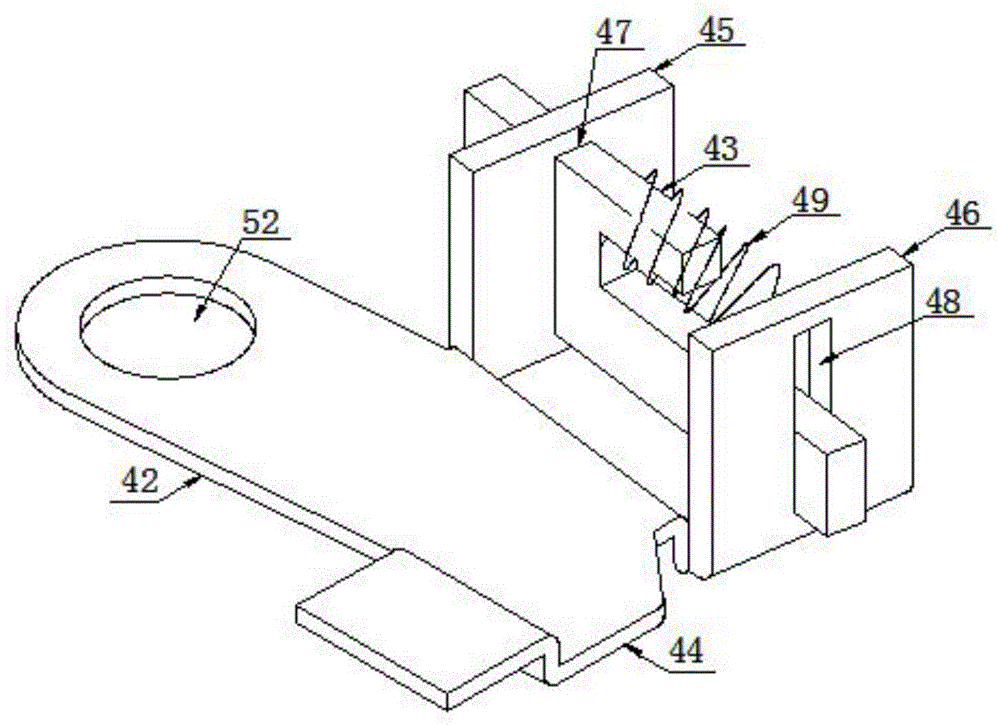
The invention relates to a locking control mechanism for an automatic door lock. The locking control mechanism comprises a lock tongue element, a trigger component, a locking component, a pusher and a middle trigger component, wherein the middle trigger component comprises a second rotating shaft arranged on a bottom plate or a cover plate, and a middle trigger part rotatably arranged on the second rotating shaft; a slideway is arranged on the middle trigger part, a sliding locking part which is in limited blocking collision fit is arranged in the slideway in a reciprocating sliding mode, and the sliding locking piece is forced by a locking bias pressure; when in a locking state, the torque of the sliding locking piece on the second rotating shaft due to a limiting blocking force is directionally opposite to that of the middle trigger part on the second rotating shaft due to a triggering force, and the middle trigger part rotates around the second rotating shaft towards the direction against the locking bias pressure during triggering. The automatic door lock with the locking control mechanism not only reliably locks, but also can be sensitively locked.

Description

technical field [0001] The invention relates to a mechanical automatic lock, in particular to a lock-out control mechanism of an automatic door lock. Background technique [0002] At present, in the prior art, the automatic locking mechanism of the mechanical lock after unlocking has been proposed; in the existing door locks, the actuating device of the locking control mechanism is provided for further controlling the locking of the bolt member. sports. Chinese patent document CN2849050Y discloses a lock-out control mechanism for an automatic door lock, which includes a lock trigger assembly and a lock assembly, and the lock trigger assembly includes a hollow contact rod slidably mounted on the lock bolt member , a release bias force exerts a bias force that causes the trigger end to protrude from the front panel, a positioning bias force of the slide pin applies a bias force away from the trigger end to a slide pin disposed in the hollow; the lock The locking assembly is ...

Claims


Application Information

Patent Timeline
Patent Type & Authority Patents(China)
IPC IPC(8): E05B63/20
Inventor 王斌坚
Owner WONLY SECURITY & PROTECTION TECH CO LTD
Learn More