Sliding rail assembly

A technology of slide rail assembly and locking parts, which is applied in the direction of bearings, linear motion bearings, shafts, etc.

Active Publication Date: 2018-03-06
KING SLIDE WORKS CO LTD +1
View PDF9 Cites 5 Cited by
  • Summary
  • Abstract
  • Description
  • Claims
  • Application Information

AI Technical Summary

Problems solved by technology

as in the case Image 6 , Figure 7 and Figure 8 It can be seen that when the second rail (20) is pulled out in an extending direction relative to the first rail (10), a latching portion (74) of the latching member (68) will abut against the first rail ( 10) A retaining end (18) of the positioning portion (16) prevents the second rail (20) from moving in a retracting direction relative to the first rail (10)

Method used


Image

  • Sliding rail assembly
  • Sliding rail assembly
  • Sliding rail assembly

Examples


Embodiment Construction

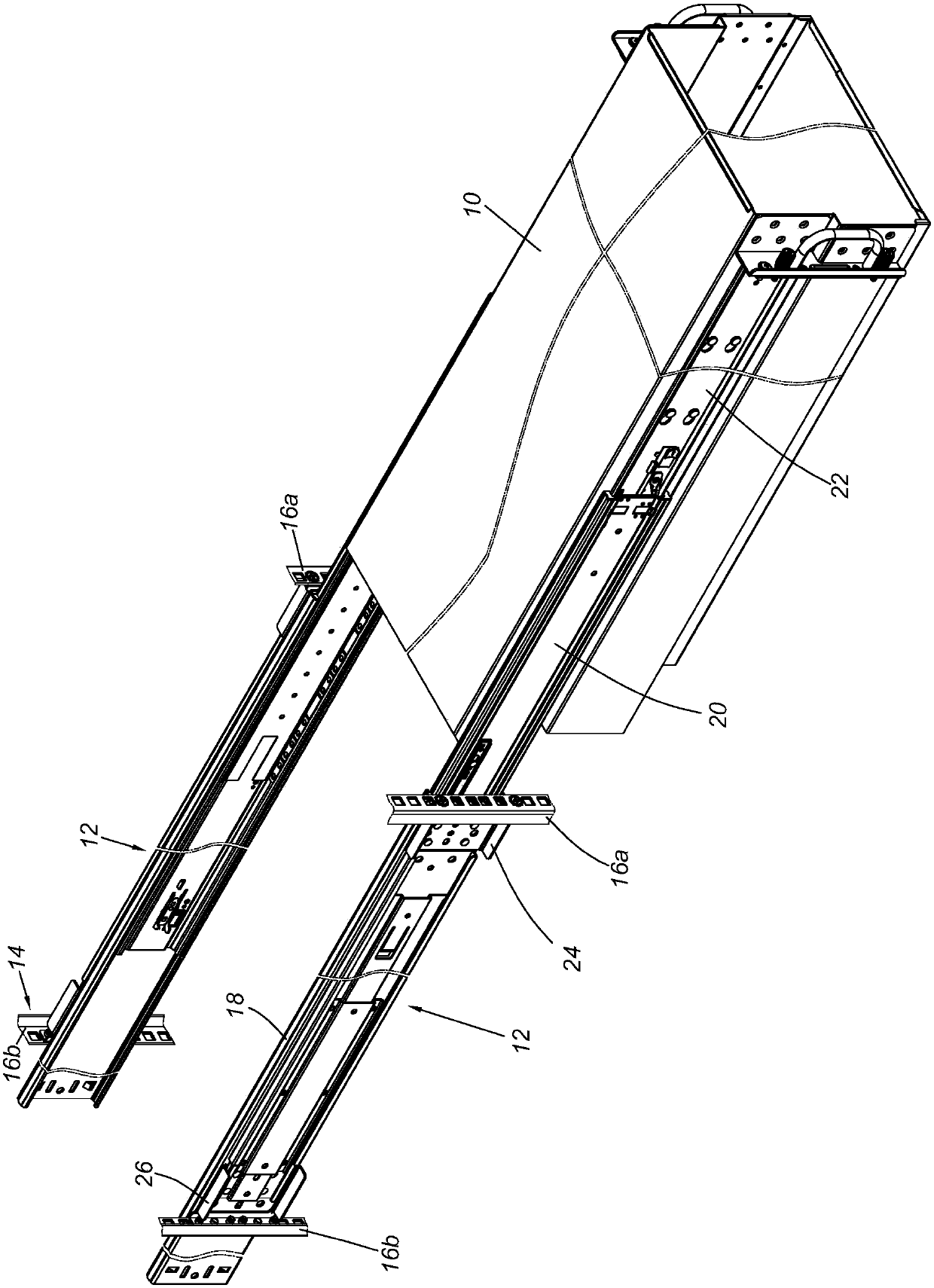
[0037] figure 1 A load 10 is shown mounted to a frame 14 by means of a pair of slide rail assemblies 12 . The carrier 10 may be a chassis of an electronic device or a drawer or the like. The rack 14 includes a pair of first machine columns 16a and a pair of second machine columns 16b. Specifically, each sliding rail assembly 12 includes a first rail 18 , a second rail 20 and a third rail 22 . The two parts of the first rail 18 can be respectively configured with a first bracket 24 and a second bracket 26 for being respectively installed on the first column 16 a and the second column 16 b of the frame 14 . In addition, the third rail 22 is used for mounting the carrier 10 . According to this configuration, with the second rail 20 and the third rail 22 being in an extended state relative to the first rail 18 , the load 10 can be located outside the frame 14 .

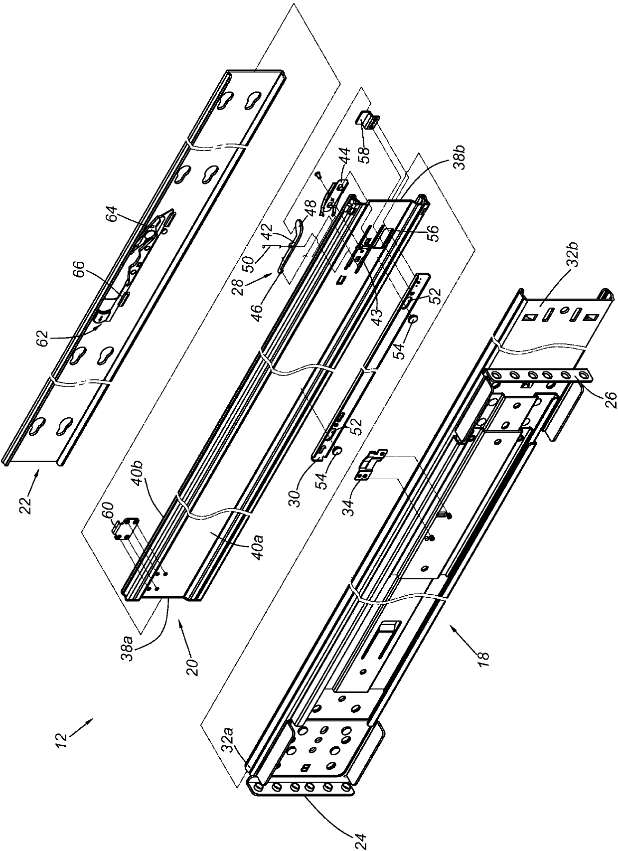
[0038] figure 2 The exploded state of the first rail 18 , the second rail 20 and the third rail 22 of the slide ...


PUM


Abstract

The invention relates to a sliding rail assembly which comprises a first rail body, a second rail body, a third rail body, a locking part and an operating part, wherein the second rail body can move relative to the first rail body from a first position to a second position; the third rail body can move relative to the second rail body; the locking part is mounted on the second rail body; when thesecond rail body is located at the second position, the locking part can lock one part of the first rail body, and thus the second rail body cannot move relative to the first rail body from the secondposition to the first position; and the operating part can be provided for being operated by a user, and thus the locking effect of the locking part on the part of the first rail body can be eliminated.

Description

technical field [0001] The invention relates to a slide rail assembly, in particular to a slide rail assembly which can be operated by an operating member to release the locking relationship between two slide rails. Background technique [0002] Generally speaking, the slide rail assembly usually includes at least two slide rails, and these slide rails can move and displace relative to each other, so that the slide rail assembly has an extended or retracted state. [0003] For example, US Patent No. US 7,677,679 B2 discloses a slide rail assembly, which includes a first rail (10), a second rail (20) and a third rail (30). The first rail (10) includes a blocking portion (14) and a block (16); the second rail (20) has a blocking piece (28) and a groove (26) for accommodating a retaining pin (40 ). When the three rails are in a fully extended state, the holding pin (40) and the catch (28) are respectively blocked by the stopper (14) and the block (16) of the first rail (10), ...

Claims


Application Information

Patent Timeline
Patent Type & Authority Applications(China)
IPC IPC(8): F16C29/02F16C29/10
CPCF16C29/005F16C29/02F16C29/10F16C2314/72F16C2380/00
Inventor 陈庚金杨顺和翁宗宪王俊强
Owner KING SLIDE WORKS CO LTD
Why Eureka
Try Eureka