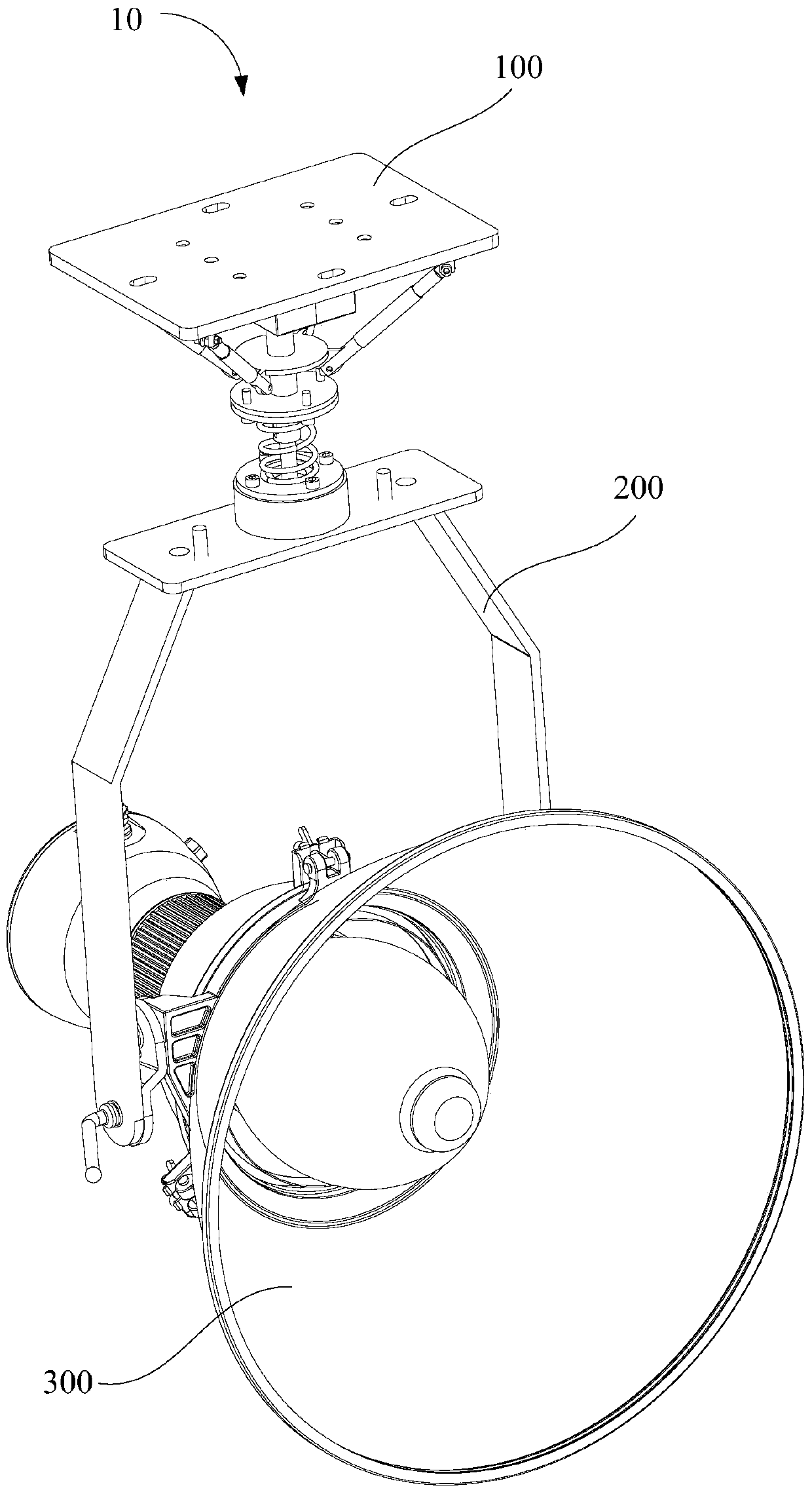
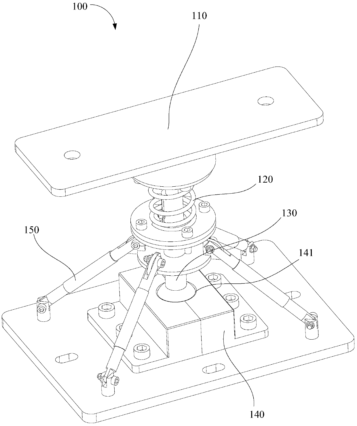
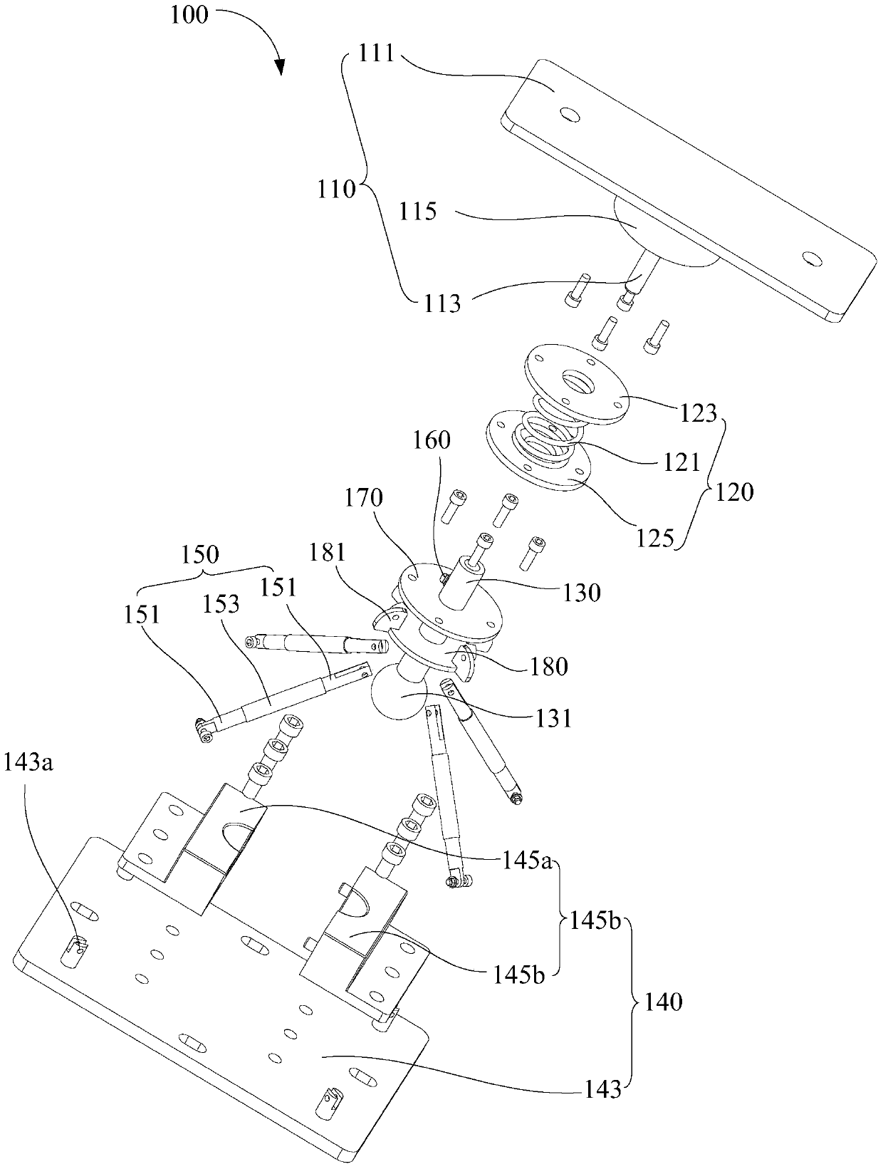
Vibration-absorbing base of lamp and floodlight adopting the vibration-damping base

A technology of lamps and sockets, which is applied in the field of floodlights, can solve the problems of broken bulbs of light sources, swaying and shaking of light sources, extinguishing of lamps, etc., and achieve the effects of increasing service life, reducing maintenance costs, and improving stability

Active Publication Date: 2018-02-06
SHENZHEN OCEANS KING LIGHTING ENG CO LTD +1
View PDF6 Cites 0 Cited by
  • Summary
  • Abstract
  • Description
  • Claims
  • Application Information

AI Technical Summary

Problems solved by technology

[0002] The mounting base of the existing lamps generally does not have an anti-vibration design, and is easily affected by external vibrations in places with strong vibrations
Under the action of vibration, it is easy to loosen the structural parts inside the lamp, resulting in failure of the internal structural connection
At the same time, external vibration also has a negative impact on the light source inside the lamp body. When the vibration is easy to cause the light source to sway and shake, the light source will be out of contact with the lamp holder and the lamp will go out. In severe cases, the bulb shell of the light source will be broken, reducing the use of the light source. life

Method used


Image

  • Vibration-absorbing base of lamp and floodlight adopting the vibration-damping base
  • Vibration-absorbing base of lamp and floodlight adopting the vibration-damping base
  • Vibration-absorbing base of lamp and floodlight adopting the vibration-damping base

Examples


Embodiment Construction

[0033] In order to facilitate the understanding of the present invention, the present invention will be described more fully below with reference to the associated drawings. Preferred embodiments of the invention are shown in the accompanying drawings. However, the present invention can be embodied in many different forms and is not limited to the embodiments described herein. On the contrary, these embodiments are provided to make the understanding of the disclosure of the present invention more thorough and comprehensive.

[0034] It should be noted that when an element is referred to as being “fixed” to another element, it can be directly on the other element or there can also be an intervening element. When an element is referred to as being "connected to" another element, it can be directly connected to the other element or intervening elements may also be present. The terms "vertical," "horizontal," "left," "right," and similar expressions are used herein for purposes ...


PUM


Abstract

The invention discloses a damping base for a lamp. The damping base comprises a carrying seat, an elastic seat, a movable support rod, a bulb mounting seat provided with a spherical groove, and a plurality of pull rods with elastically-adjustable lengths, wherein the carrying seat comprises a fixing plate and a guide column which is vertical to the fixing plate; the elastic seat comprises an elastic part, an upper mounting plate and a lower mounting plate; the two ends of the elastic part are fixedly connected with the upper mounting plate and the lower mounting plate respectively; both the upper mounting plate and the lower mounting plate are correspondingly provided with through holes; the guide column passes through the through hole of the upper mounting plate; one end of the movable support rod passes through the through hole of the lower mounting plate, and is in sliding sleeve connection with the free end of the guide column; a bulb is arranged at the other end of the movable support rod; the bulb is arranged in the spherical groove, and can rotate freely in the spherical groove; the two ends of each pull rod are rotationally connected with the middle part of the movable support rod and the bulb mounting seat respectively. The damping base has the advantages of achieving a good damping effect, prolonging the light source service life of the lamp and reducing the maintenance cost of the lamp. The invention further provides a projection lamp adopting the damping base.

Description

【Technical field】 [0001] The invention relates to a vibration-damping structure of a lamp, in particular to a vibration-damping base of a lamp and a projection lamp using the vibration-damping base. 【Background technique】 [0002] The mounting bases of existing lamps generally do not have an anti-vibration design, and are easily affected by external vibrations in places with strong vibrations. Under the action of vibration, it is easy to loosen the structural parts inside the lamp, resulting in failure of the internal structural connection. At the same time, external vibration also has a negative impact on the light source inside the lamp body. When the vibration is easy to cause the light source to sway and shake, the light source will be out of contact with the lamp holder and the lamp will go out. In severe cases, the bulb shell of the light source will be broken, reducing the use of the light source. life. 【Content of invention】 [0003] In view of the above situatio...

Claims


Application Information

Patent Timeline
Patent Type & Authority Patents(China)
IPC IPC(8): F21S8/00F21V15/04F21V21/108
CPCF21S8/00F21V15/04F21V21/108
Inventor 周明杰李鹏飞
Owner SHENZHEN OCEANS KING LIGHTING ENG CO LTD
Why Eureka
Try Eureka