
Fault detection method and device for air conditioner

A technology for fault detection and air conditioners, applied in space heating and ventilation, heating methods, lighting and heating equipment, etc., can solve problems such as low fault detection efficiency, and achieve the effects of improving fault detection efficiency, accurate control, and improving efficiency

Active Publication Date: 2017-11-14
GREE ELECTRIC APPLIANCES INC
View PDF5 Cites 0 Cited by
  • Summary
  • Abstract
  • Description
  • Claims
  • Application Information

AI Technical Summary

Problems solved by technology

[0004] The main purpose of the present invention is to provide a fault detection method and device for an air conditioner to solve the problem in the prior art that the staff need to climb to the ceiling to operate the air conditioner when debugging the air conditioner, resulting in low fault detection efficiency

Method used


Image

  • Fault detection method and device for air conditioner
  • Fault detection method and device for air conditioner
  • Fault detection method and device for air conditioner

Examples


Embodiment Construction

[0022] It should be noted that, in the case of no conflict, the embodiments in the present application and the features in the embodiments can be combined with each other. The present invention will be described in detail below with reference to the accompanying drawings and examples.

[0023] In order to enable those skilled in the art to better understand the solutions of the present invention, the following will clearly and completely describe the technical solutions in the embodiments of the present invention in conjunction with the drawings in the embodiments of the present invention. Obviously, the described embodiments are only It is an embodiment of a part of the present invention, but not all embodiments. Based on the embodiments of the present invention, all other embodiments obtained by persons of ordinary skill in the art without making creative efforts shall fall within the protection scope of the present invention.

[0024] It should be noted that the terms "fir...


PUM


Abstract

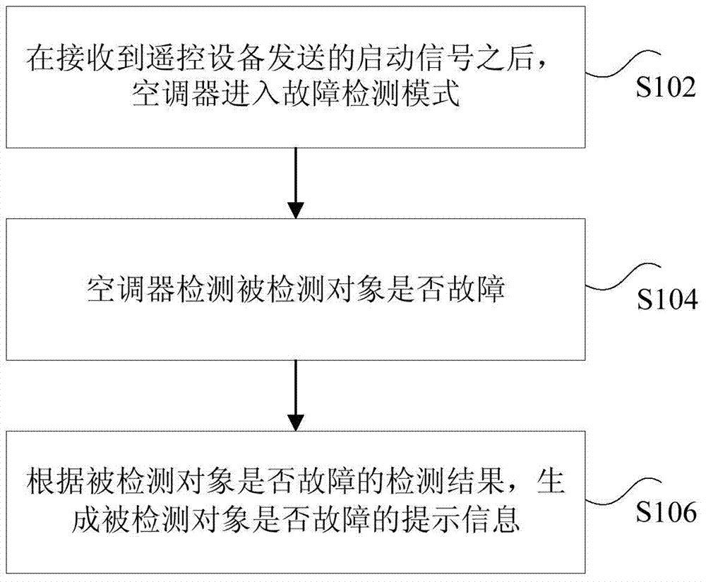
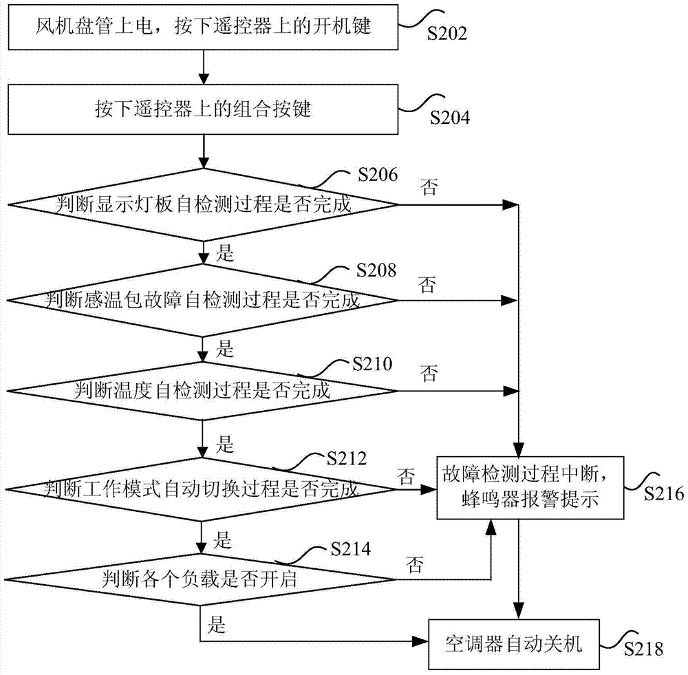
The invention discloses a method and a device for detecting faults of an air conditioner. The method comprises the following steps of enabling the air conditioner to enter a fault detecting mode when receiving starting signals which are transmitted by remote control equipment and contain information of a detected object of the air conditioner; detecting whether the detected object of the air conditioner fails or not; and generating prompt messages about the fault of the detected object according to a detection result on the detected object. By the method and the device for detecting the faults of the air conditioner, the problems that when a worker debugs an air conditioner in the prior art, the worker needs to climb to a ceiling and operate the air conditioner, and the fault detection efficiency is low are solved, and an effect of improving the fault detection efficiency of the air conditioner is achieved.

Description

technical field [0001] The invention relates to the field of air conditioner control, in particular to a fault detection method and device for an air conditioner. Background technique [0002] After the fan coil unit at the end of the air conditioner is installed, it needs to be debugged, and the ceiling can only be sealed after the debugging is qualified. In the prior art, the debugging of the fan coil unit is carried out by using the AUTO key on the mainboard controller. This method requires engineering installation personnel to climb to the ceiling and manually press the AUTO key on the mainboard controller to perform debugging and operation of various air-conditioning modes (such as cooling mode, heating mode, etc.), which is not only time-consuming and labor-intensive but also quite dangerous; and, The AUTO key on the motherboard controller can only switch the air-conditioning mode, but cannot detect the failure of the display lamp board, temperature and related loads ...

Claims


Application Information

Patent Timeline
Patent Type & Authority Patents(China)
IPC IPC(8): F24F11/00
CPCF24F11/30F24F11/52
Inventor 陈群贞文武任鹏陈万兴
Owner GREE ELECTRIC APPLIANCES INC
Learn More