
Switch cabinet group

A switchgear and switchgear technology, applied in the field of switchgear, can solve the problems of easy picking, damage, illegal intrusion, etc., and achieve the effect of reducing the difficulty and complexity of storage

Inactive Publication Date: 2015-04-29
WUHU JINNIU ELECTRIC
View PDF3 Cites 1 Cited by
  • Summary
  • Abstract
  • Description
  • Claims
  • Application Information

AI Technical Summary

Problems solved by technology

This protection method has many deficiencies, such as: poor protection ability, criminals can easily pick the lock to illegally intrude and destroy

Method used


Image

  • Switch cabinet group

Examples


Embodiment

[0022] In the switch cabinet group according to the embodiment of the present invention, the switch cabinet group includes:

[0023] switchgear, the switchgears are respectively installed in the at least two switchgears; the switchgear and wiring methods are existing technologies in the field, and will not be repeated here;

[0024] A key, the switchgears of the at least two switchgears share the key; use the same key to start or close the switchgears in different switchgears;

[0025] The input ends of the at least two switch cabinets correspond to different power sources respectively, and the output ends are paralleled; thus, different switch cabinets are connected to different power sources, but the outputs are all powered by the same load;

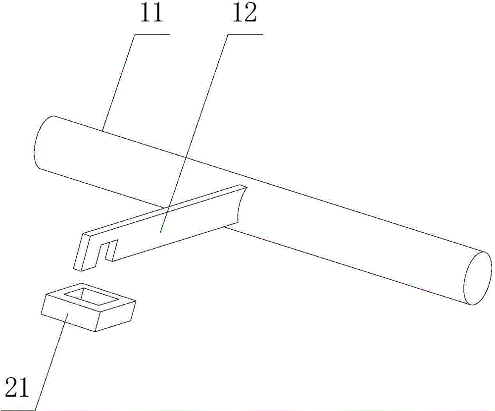
[0026] figure 1 Schematically provides the basic structural diagram of the door lock of the embodiment of the present invention, as figure 1 As shown, the door lock is installed on each switch cabinet, specifically including:

[002...


PUM


Abstract

The invention provides a switch cabinet group which comprises at least two switch cabinets, switchgears and a key, wherein the switchgears are mounted in the at least two switch cabinets respectively and share the key; and input ends of the at least two switch cabinets correspond to different power sources respectively. The switch cabinet group has the advantages of simple structure, safety and the like.

Description

technical field [0001] The present invention relates to switch cabinets, in particular to switch cabinet groups. Background technique [0002] In some industries, such as medical and metallurgical industries, it is necessary to ensure continuous power supply. When one of the power lines fails, the other power line must be connected as soon as possible. The current practice is to provide at least two switch cabinets, different circuits are connected to different switch cabinets, the outputs of the switch cabinets are paralleled, each switch cabinet is equipped with different locks and keys, and the keys are used to connect and close. [0003] In order to prevent the cabinet door from being accidentally opened, a door lock is installed on the cabinet door. This protection method has many shortcomings, such as: poor protection ability, criminals are easy to pick the lock and illegally invade and destroy. Contents of the invention [0004] In order to solve the above-mention...

Claims


Application Information

Patent Timeline
IPC IPC(8): H02B1/26
CPCH02B1/306E05C19/12
Inventor 沈启军刘朝锋黄志才
Owner WUHU JINNIU ELECTRIC
Learn More