A mobile phone battery charger

A mobile phone battery and charger technology, applied to battery circuit devices, current collectors, electric vehicles, etc., can solve the problems of troublesome production and installation, low strength, short service life, etc., achieve convenient production and installation, prolong service life, The effect of low market prices

Active Publication Date: 2017-02-22
ZHEJIANG MINGLEI TOOLS IND
View PDF3 Cites 0 Cited by
  • Summary
  • Abstract
  • Description
  • Claims
  • Application Information

AI Technical Summary

Problems solved by technology

[0003] For example, the invention patent with the authorized notification number of CN 102723759 A discloses a mobile phone battery charger, which includes parts such as a cover, a bottom cover, and a casing formed by a decorative frame placed therebetween. Elastic and distance-adjustable clips, the battery is placed on the surface of the casing and clamped by the clips, which effectively solves the problem that the battery is easy to fall off, but it also has the following technical problems. 1. First, the charging structure is too large Complicated, there are many parts in the charger, and the production and installation are troublesome, which makes the production cost of the charger higher, resulting in a higher market price of the charger and a lower market share; 2. The charger is different from the existing Like most chargers, an elastic clamp is installed on the charger to clamp the battery, but this elastic clamp is easily damaged and has a short service life. After damage, the battery cannot be clamped, and the charger itself It can be used, thus causing unnecessary waste; 3, the charger is equipped with a energized and adjustable contact pin, which is connected to the positive and negative poles of the battery. Due to its low strength, the contact pin It is easy to be broken and damaged during the adjustment process, causing the charger to be unable to connect normally with the battery

Method used


Image

  • A mobile phone battery charger
  • A mobile phone battery charger
  • A mobile phone battery charger

Examples


Embodiment Construction

[0026] The following are specific embodiments of the present invention and in conjunction with the accompanying drawings, the technical solutions of the present invention are further described, but the present invention is not limited to these embodiments.

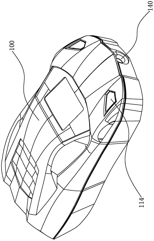
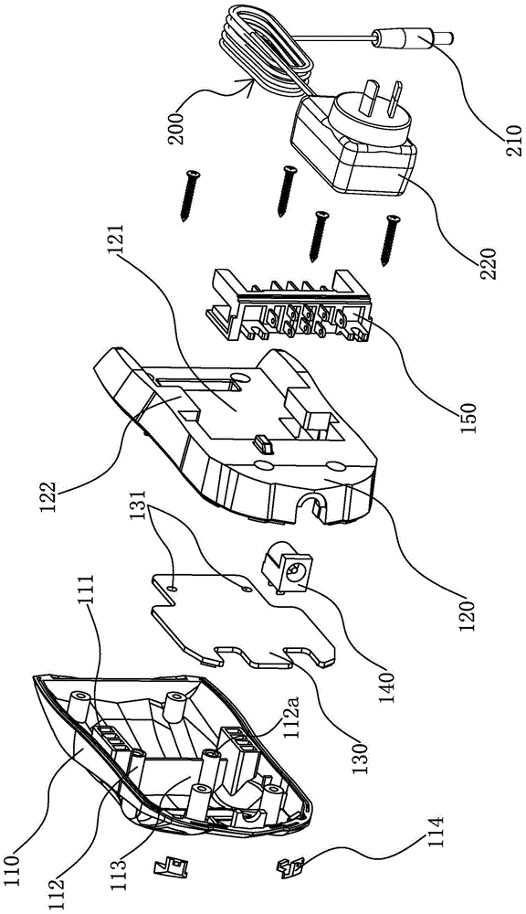
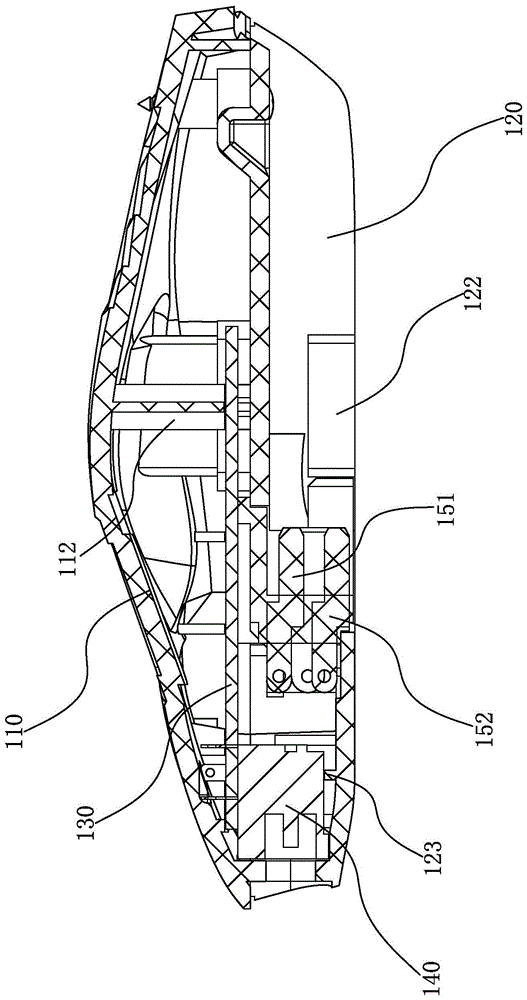
[0027] Such as figure 1 with figure 2 As shown, a mobile phone battery charger of the present invention includes a car model casing 100, the casing 100 includes a closed upper casing 110 and a lower casing 120, and an accommodating cavity is formed between the upper casing 110 and the lower casing 120 .

[0028] A PCB circuit board 130 is arranged in the accommodating chamber, and a DC joint 140 clamped by the upper case 110 and the lower case 120 and electrically connected with the PCB circuit board 130 is installed in the middle of the front end of the accommodating chamber, and the connecting hole of the DC joint 140 Out of the shell 100, it is used to connect with the power supply, which is convenient for charging a...


PUM


Abstract

The invention provides a mobile phone battery charger, belongs to the technical field of chargers, and solves the technical problems that the conventional charger is complex in structure and shorter in service life and is easily damaged. The mobile phone battery charger comprises a shell, wherein a printed circuit board is arranged in the shell, and a support is arranged on the lower surface of the shell; a first contact piece group and a second contact piece group are arranged on the support; the first contact piece group comprises a plurality of upper contact pieces which are transversely and vertically arranged on the support, and the second contact piece group comprises a plurality of lower contact pieces which are transversely arranged and correspond to the upper contact pieces; both the upper contact pieces and the lower contact pieces are electrically connected with the printed circuit board. The parts of the whole structure are less, and the mobile phone battery charger is convenient to manufacture and mount. The first contact piece group and the second contact piece group are fixedly connected with the support, so that the fixing effect is good, the contact piece groups are not easily damaged, and the strength of the contact pieces are high. As the contact pieces are fixedly connected with the support, the contact pieces are not easily damaged, and the service life is prolonged.

Description

technical field [0001] The invention belongs to the technical field of chargers and relates to a mobile phone battery charger. Background technique [0002] The mobile phone battery charger is another form of charger relative to the mobile phone direct charging charger. Its main purpose is to charge the mobile phone battery. The existing battery charger fixes the battery on the charger and realizes it by connecting it to the power supply. battery charging. [0003] For example, the invention patent with the authorized notification number of CN 102723759 A discloses a mobile phone battery charger, which includes parts such as a cover, a bottom cover, and a casing formed by a decorative frame placed therebetween. Elastic and distance-adjustable clips, the battery is placed on the surface of the casing and clamped by the clips, which effectively solves the problem that the battery is easy to fall off, but it also has the following technical problems. 1. First, the charging str...

Claims


Application Information

Patent Timeline
Patent Type & Authority Patents(China)
IPC IPC(8): H02J7/00
CPCH02J7/0045
Inventor 翁磊
Owner ZHEJIANG MINGLEI TOOLS IND
Why Eureka
Try Eureka