Stator

a stator and cylinder technology, applied in the field of stators, can solve the problems of difficult mechanization work, uneven torque, uneven force generation density in a running direction, etc., and achieve the effect of higher coil end, higher-performance stators, and higher occupancy ratios in the slots

Inactive Publication Date: 2011-04-12
TOYOTA IND CORP
View PDF10 Cites 5 Cited by
  • Summary
  • Abstract
  • Description
  • Claims
  • Application Information

AI Technical Summary

Benefits of technology

[0012]It is an object of the present invention to provide a spirally wound stator which achieves the mechanization of the work of inserting a wound coil in the slot of a stator core and a high market share.
[0014]In the stator of the present invention, the work of inserting a wound coil in the slot of its core can be mechanized. When it is used for a motor, its torque unevenness is small and the vibration and noise of the motor can be reduced. Simultaneously, its coil end is short, its height is fairly uniform and compact and also the coil occupancy in the slot is high.
[0022]According to the above-described aspects, since in the one-layer loop between coils overlapped in the above-described spiral, one side of each coil constituting the one-layer loop is inserted in each slot, when the loop between coils overlapped in the above-described spiral is overlapped in two or more layers, the overlap between coils in its radius direction becomes more uniform and their coil ends becomes more uniform and compact. Therefore, the coil occupancy ratio in the slot can be made higher and the coil end becomes shorter to obtain a higher-performance stator.
[0023]According to the present invention, the work of inserting a wound coil in the slot of a stator core can be mechanized. When it is used for a motor, its torque unevenness is small and the vibration and noise of the motor can be reduced. Furthermore, a stator in which the coil end is short, the coil height is fairly uniform and compact and also the coil occupancy ratio in the slot is high can be provided.

Problems solved by technology

However, since these methods can form only a coil in which each magnetic pole is concentrically wound, a motor using such a stator core causes torque unevenness due to a phenomenon that the magnetic force generation density in a running direction becomes uneven.
However, in the above-described spirally coiled stator, each of both sides of a coil must be inserted in a slot while overlapping it on another coil and it is difficult to mechanize the work.
Therefore, since a coil wound in advance must be manually inserted in the slot of the stator core, its manufacturing workability is low and its manufacturing costs becomes high.
However, the above-described Patent Documents 1 and 2 do not disclose a method for mechanizing the work of inserting a wound coil in the slot of the stator core.
Therefore, the coil must be manually inserted, a motor cannot be manufactured industrially in low costs and in high coil occupancy.

Method used


Image

  • Stator
  • Stator
  • Stator

Examples


Embodiment Construction

[0086]The preferred embodiments of the present invention are described below with reference to the drawings.

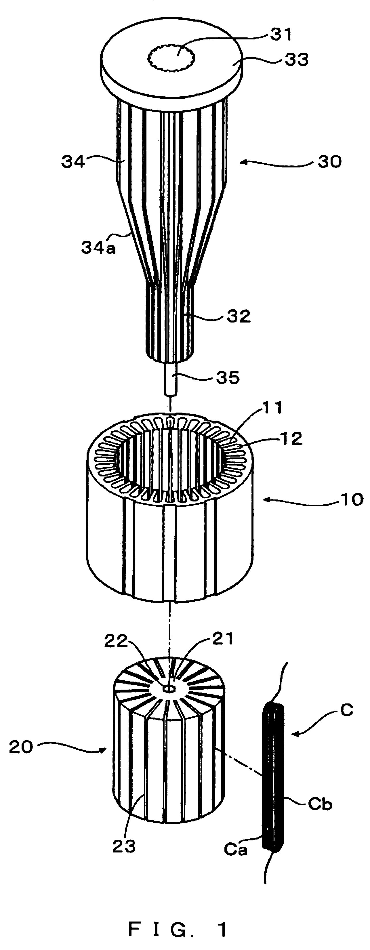
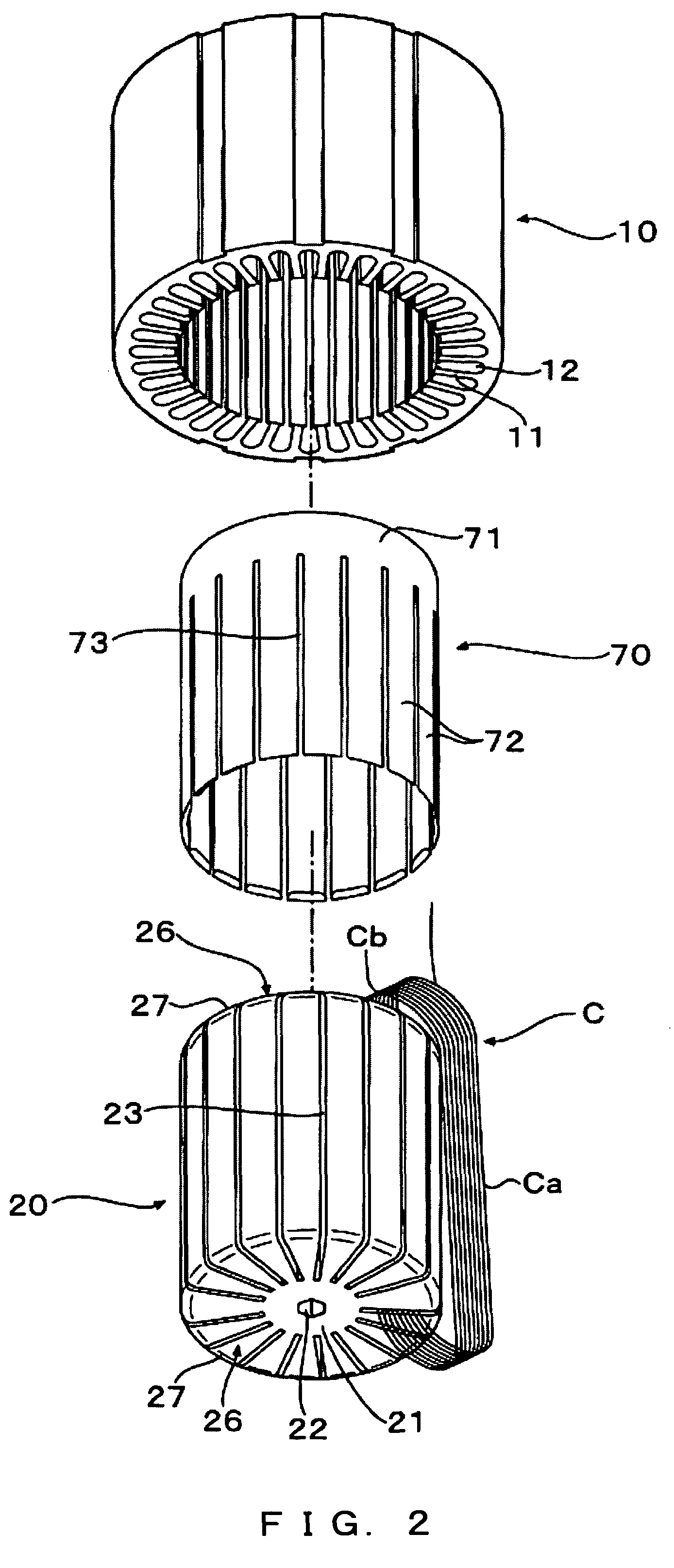
[0087]FIGS. 1 and 2 show one example of the device for manufacturing the stator of the present invention.

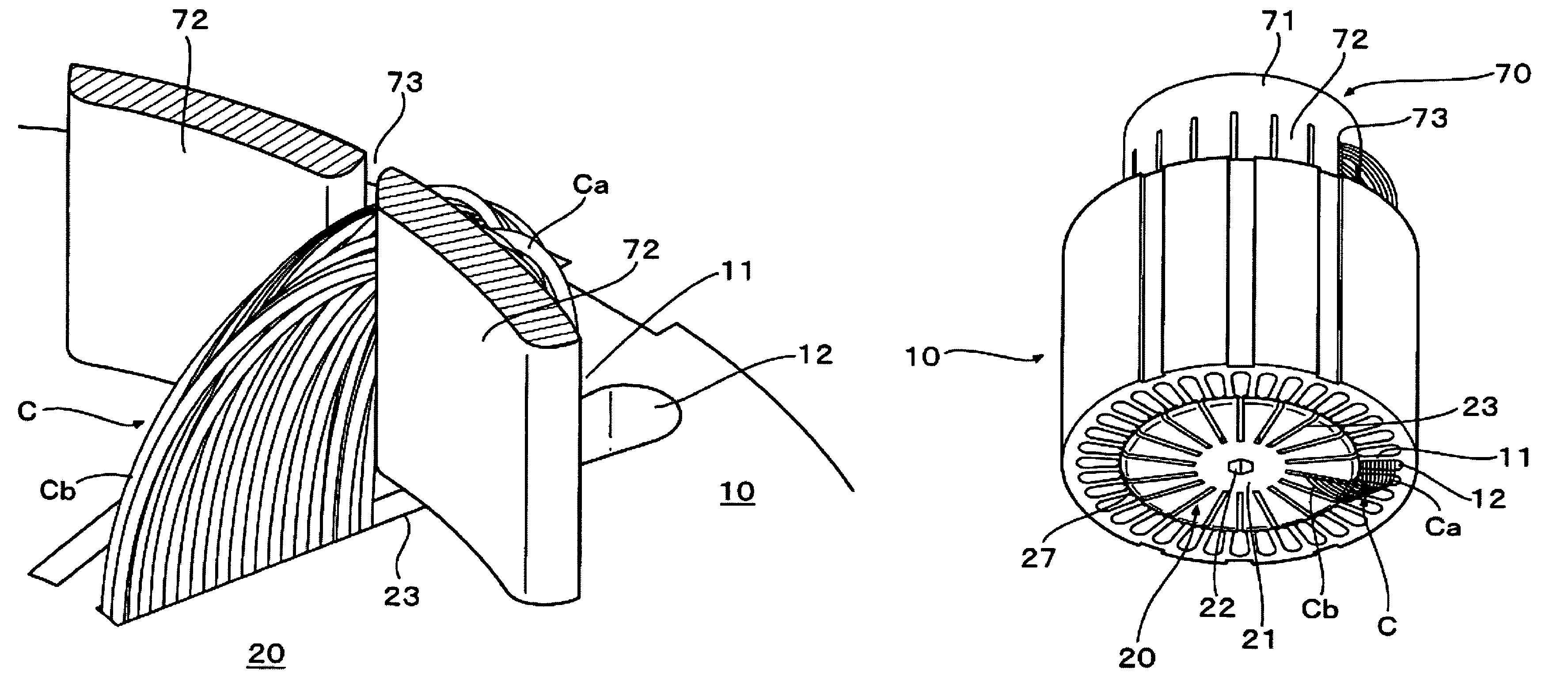
[0088]In FIGS. 1 and 2, a reference numeral 10 is a stator core and the stator core 10 comprises inner teeth 11 in its inner perimeter. Then, a slot 12 is formed between the inner teeth 11.

[0089]This manufacturing device comprises a jig 20 almost cylindrical as a whole, which is inserted in the inner perimeter of the stator core 10. The jig 20 comprises a shaft unit 21 at the center, a hole 22 provided at the center of the top end surface of this shaft unit 21 and a plurality of holding grooves 23 radiantly formed from the outer perimeter of the shaft unit 21 toward the cylindrical outer perimeter of the shaft unit 21.

[0090]The holding grooves 23 are formed with a pitch integer times as that of the slot 12 of the stator core 10. Although in the case of this example, the hol...


PUM


Abstract

The present invention provides a stator coiled in a spiral, capable of mechanically inserting a wound coil in the slot of a stator core. In a stator in which coils are overlapped in a spiral when viewed from the end surface of the stator core after each of one sides of a plurality of coils wound in advance is inserted in the slot of the stator core and each of the other sides of the plurality of coils is inserted in a different slot, by repeating the inserting operation twice or more, the loop of the coils overlapped in a spiral are piled in two layers or more in the radius direction of the stator core and the total coil sectional area inserted in the slots of the stator core is larger than a prescribed value based on the inside radius of the stator core.

Description

BACKGROUND OF THE INVENTION[0001]1. Field of the Invention[0002]The present invention relates to a stator in which one side of each of a plurality of coils wound in advance is inserted in the slot of its core and then the other side of each of the plurality of coils is inserted in another slot and the coils overlap each other in a spiral when viewed from the end surface of the stator core.[0003]2. Description of the Related Art[0004]As the manufacturing method of a stator with a wound coil, a direct winding method of winding in series a coil wound around the inner teeth of the stator core and a coil insertion method of inserting a coil wounded in advance in the slot of the stator core are mainly known.[0005]However, since these methods can form only a coil in which each magnetic pole is concentrically wound, a motor using such a stator core causes torque unevenness due to a phenomenon that the magnetic force generation density in a running direction becomes uneven. Since this torque...

Claims


Application Information

Patent Timeline
Patent Type & Authority Patents(United States)
IPC IPC(8): H02K1/00
CPCH02K15/067
Inventor YAMAGUCHI, KAZUYUKIENDO, KENJIKATO, YOSHIO
Owner TOYOTA IND CORP
Why Eureka
Try Eureka