Electronic device

A technology of electronic devices and heat sources, applied in the direction of cooling/ventilation/heating transformation, etc., can solve the problems of easy damage, incomplete heat dissipation of rear components, etc.

Inactive Publication Date: 2015-04-29
INVENTEC PUDONG TECH CORPOARTION +1
View PDF4 Cites 5 Cited by
  • Summary
  • Abstract
  • Description
  • Claims
  • Application Information

AI Technical Summary

Problems solved by technology

As a result, the rear components often have insufficient heat dissipation and are easily damaged

Method used


Image

  • Electronic device
  • Electronic device
  • Electronic device

Examples


Embodiment Construction

[0036] The detailed features and advantages of the present invention are described in detail below in the embodiments, the content of which is sufficient to enable any person with ordinary knowledge in the art to understand the technical content of the present invention and implement it accordingly, and according to the content disclosed in the specification and the scope of the claims With the accompanying drawings, anyone with ordinary knowledge in the art can easily understand the related objects and advantages of the present invention. The following examples are to further describe the viewpoints of the present invention in detail, but not to limit the scope of the present invention in any way.

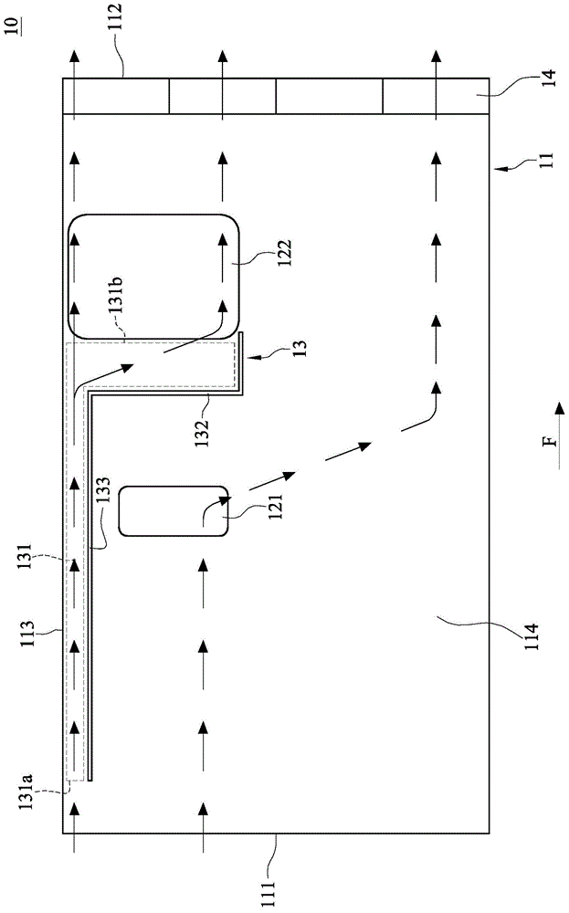
[0037] Please refer to Figure 1A , shows a structural diagram of the electronic device 10 according to an embodiment of the present invention. In this embodiment, the electronic device 10 includes a casing 11 , a first heat source 121 , a second heat source 122 , a flow guiding s...


PUM


Abstract

The invention relates to an electronic device which comprises a shell, a first heat source, a second heat source and a flow guide structure, wherein the shell is provided with an air inlet side and an air outlet side; the first heat source is arranged in the shell and positioned between the air inlet side and the air outlet side, and the second heat source is arranged in the shell and positioned between the first heat source and the air outlet side; the flow guide structure is arranged in the shell and provided with a flow channel, and an air inlet and an air outlet are respectively formed in the two opposite ends of the flow channel; the air inlet is toward the air inlet side, and the air outlet is toward the second heat source. The flow guide structure comprises a retaining wall, and the retaining wall is arranged between the first heat source and the second heat source.

Description

technical field [0001] The invention relates to an electronic device, in particular to an electronic device with multiple heat sources. Background technique [0002] While the electronic device is in operation, due to the huge amount of calculation, the calculation element used for calculation will generate a lot of heat. The storage element used to temporarily store the data computed by the computing element also generates heat. In order to make the computing device and the storage device operate smoothly, the power supply must supply power to the computing device and the storage device, and also emit a lot of heat. However, the high temperature environment will affect the operation of various components in the electronic device and easily cause damage to the components. Therefore, dissipating heat from the electronic device to reduce the ambient temperature of each component is an important issue for the relevant industry. [0003] However, nowadays, the volume requirem...

Claims


Application Information

Patent Timeline
Patent Type & Authority Applications(China)
IPC IPC(8): H05K7/20
Inventor 吴德洋
Owner INVENTEC PUDONG TECH CORPOARTION
Why Eureka
Try Eureka