Flue gas waste heat recovery device

A waste heat recovery device and recovery device technology, applied in the field of flue gas waste heat recovery, can solve the problems of user inconvenience, inconvenient cleaning operations, and affecting the use of flue gas waste heat recovery devices, and achieve the effects of prolonging the service life and avoiding corrosion

Inactive Publication Date: 2019-05-24
SHANDONG AIRPOWER ENERGY SAVING EQUIP CO LTD
View PDF0 Cites 4 Cited by
  • Summary
  • Abstract
  • Description
  • Claims
  • Application Information

AI Technical Summary

Problems solved by technology

[0004] The purpose of the present invention is to provide a flue gas waste heat recovery device to solve the problem that when the existing flue gas waste heat recovery device is used in the above-mentioned background technology, because the flue gas contains particles, waste residues and other impurities, the flue gas waste heat recovery device is absorbing The flue gas will inhale impurities such as particles and waste residues together. During the working process, the particles will accumulate, which will affect the use of the flue gas waste heat recovery device, and it is not convenient for the staff to clean up, thus affecting the flue gas waste heat recovery device. Service life, causing a certain degree of inconvenience to users

Method used


Image

  • Flue gas waste heat recovery device
  • Flue gas waste heat recovery device
  • Flue gas waste heat recovery device

Examples


Embodiment 1

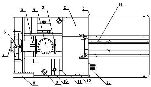
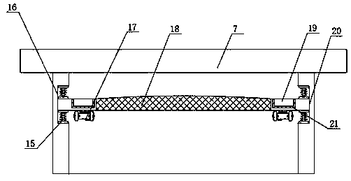
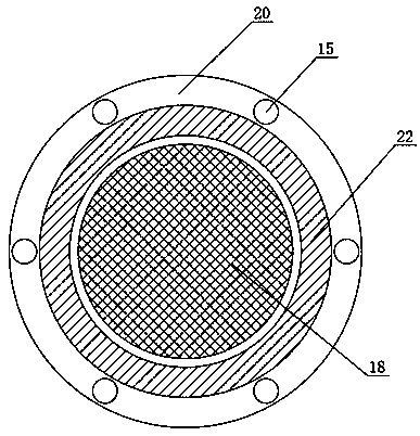
[0023] see Figure 1-Figure 3 , the present invention provides a technical solution: the flue gas waste heat recovery device, including a filter device, the filter device includes an air inlet 7, and an integrated movable groove 16 is provided on both sides of the air inlet 7, and the two sides of the movable groove 16 are passed through bolts The connection spring 15 is fixed, and the connection ring plate 20 is connected by bolts between the connection springs 15. The bottom of the connection ring plate 20 is fixed with a vibrator 17 by bolts relative to the inner side of the connection spring 15, and the top of the vibrator 17 is relatively connected to the connection ring plate 20. The surface is provided with a ring groove 22, and the inside of the ring groove 22 is connected with a collection box 19 by snap-fitting. The bottom of the collection box 19 is pasted with a magnetic block 21, and the middle part of the connecting ring plate 20 is fixed with a filter screen 18 b...

Embodiment 2

[0028] see Figure 1-Figure 5 , the present invention provides a technical solution: a flue gas waste heat recovery device, including a filter device and a cleaning device, the filter device includes an air inlet 7, and there are movable grooves 16 with an integrated structure on both sides of the air inlet 7, and there are two movable grooves inside the movable groove 16. The connecting spring 15 is fixed on the side by bolts, and the connecting ring plate 20 is connected by bolts between the connecting springs 15. The bottom of the connecting ring plate 20 is fixed with a vibrator 17 by bolts relative to the inner side of the connecting spring 15, and the top of the vibrating machine 17 is connected to the connecting spring 15. A ring groove 22 is opened on the surface of the ring plate 20, and the inside of the ring groove 22 is connected with a collection box 19 by snap-fitting. The bottom of the collection box 19 is pasted with a magnetic block 21, and the middle part of t...


PUM


Abstract

The invention discloses a flue gas waste heat recovery device. The flue gas waste heat recovery device comprises a filter device and a cleaning device, wherein the filter device comprises an air inlet, movable grooves with integrated structures are formed in the two sides in the air inlet, connecting springs are fixed to the two sides in the movable grooves, a connecting ring plate is connected between the connecting springs, a vibrator is fixed to the bottom, relative to the inner sides of the connecting springs, of the connecting ring plate, and a ring groove is formed in the top, relative to the surface of the connecting ring plate, of the vibrator; through the filter device designed in a waste heat recovery device body, dust and particles can be conveniently blocked outside the waste heat recovery device, so that the situation that the use of the waste heat recovery device is affected due to the accumulation of the dust and particles in the waste heat recovery device is avoided; and through the cleaning device arranged at the bottom of the waste heat recovery device body, workers can conveniently clean the bottom surface of the waste heat recovery device body after work is finished, and the heat dissipation of the waste heat recovery device body is prevented from being influenced by the accumulation of dust.

Description

technical field [0001] The invention belongs to the technical field of flue gas waste heat recovery, and in particular relates to a flue gas waste heat recovery device. Background technique [0002] The high-temperature flue gas discharged from various metallurgical furnaces often takes away 20-50% of the heat supplied by the furnace. The flow direction of the flue gas from the metallurgical furnace is opposite to that of the preheated medium, and the waste heat of the flue gas can be fully utilized to achieve a higher preheating. Heat temperature, the wall needs to be made of heat-resistant materials, flue gas is the main way for general energy-consuming equipment to waste energy, flue gas waste heat recovery is mainly to convert the heat carried by the flue gas into usable heat through a certain heat exchange method , in order to further improve the thermal efficiency of the kiln and achieve the purpose of saving energy and reducing consumption, recycling flue gas waste he...

Claims


Application Information

Patent Timeline
Patent Type & Authority Applications(China)
IPC IPC(8): F27D17/00
CPCY02P10/25
Inventor 张伟吴卫平吴琛张伟东魏忠鑫窦秀华李文杰庾振东蔺立英吴涛姬铖赵俊甲王林华
Owner SHANDONG AIRPOWER ENERGY SAVING EQUIP CO LTD
Why Eureka
Try Eureka