High-voltage direct-current transformer connected with diode clamping power switch in series

A diode clamping and power switching technology, applied in the direction of converting DC power input to DC power output, AC power input converting to DC power output, output power conversion device, etc. Unbalanced voltage, high static voltage and other problems, to achieve the effect of increasing cost and complexity, reducing hardware cost and requiring less

Active Publication Date: 2016-03-16
BEIJING INSTITUTE OF TECHNOLOGYGY
View PDF4 Cites 4 Cited by
  • Summary
  • Abstract
  • Description
  • Claims
  • Application Information

AI Technical Summary

Problems solved by technology

Unsynchronized gate drive signals can cause voltage spikes and high quiescent voltages on devices that lag during turn-on, resulting in unbalanced voltage across power switches
The degree of asynchrony of the gate drive signal depends on the control circuit and the transmission line between the control circuit and the gate drive, so the degree of asynchrony is difficult to predict in advance

Method used


Image

  • High-voltage direct-current transformer connected with diode clamping power switch in series
  • High-voltage direct-current transformer connected with diode clamping power switch in series
  • High-voltage direct-current transformer connected with diode clamping power switch in series

Examples


Embodiment 1

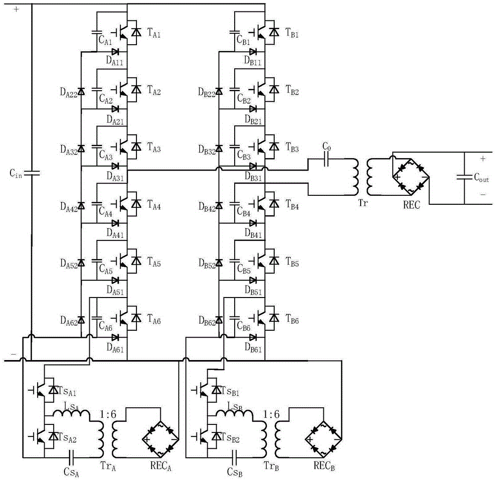
[0026] Embodiment 1: Take 12 diode-clamped power switches connected in series as an example to illustrate.

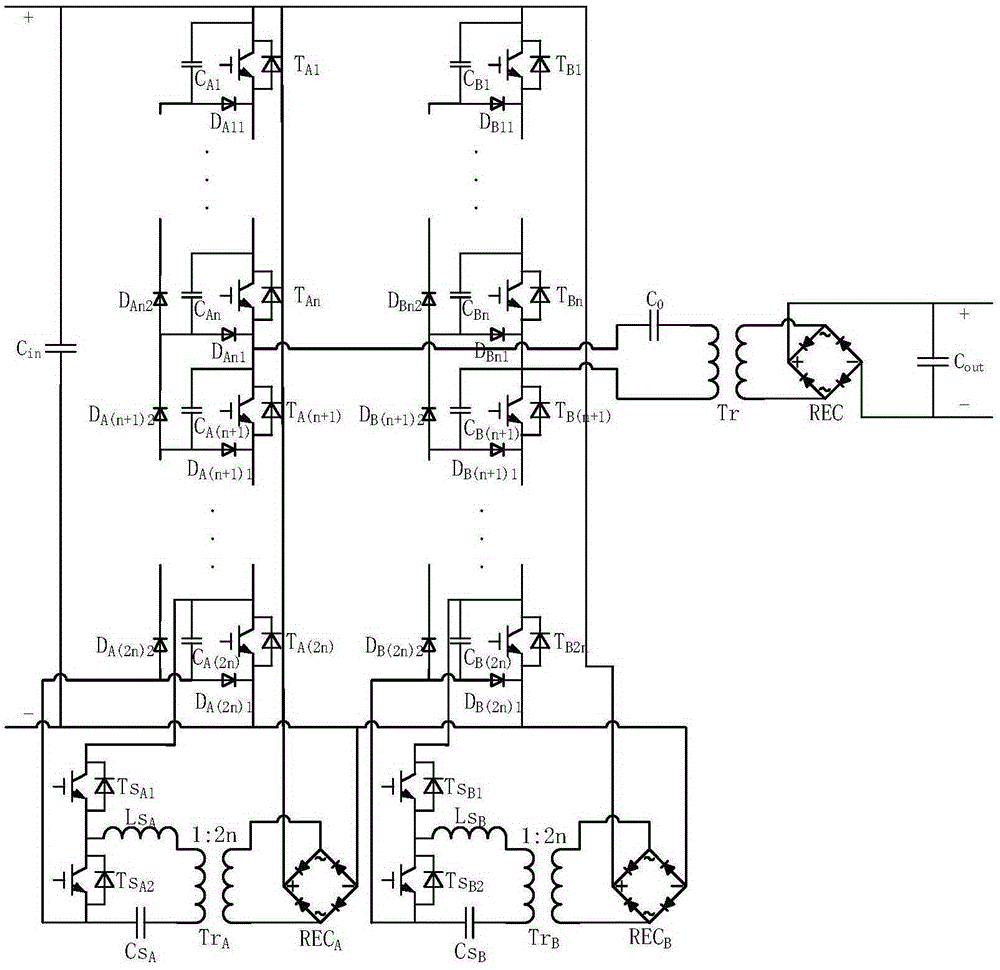
[0027] like image 3 As shown, a unidirectional diode-clamped power switch series high-voltage DC transformer disclosed in this embodiment includes an input-side DC bus capacitor C in , DC blocking capacitor C 0 , high-frequency transformer Tr, single-phase rectifier bridge REC, output side DC bus capacitor C out and an auxiliary circuit, the auxiliary circuit is divided into an A-way auxiliary circuit and a B-way auxiliary circuit. It also includes two-way parallel single-way topology (A, B), which are respectively A-way topology and B-way topology. The single-way topology (A, B) is used to make the capacitors contained in the topology Balance the voltage between the power switches and balance the voltage between the power switches. At the same time, the single-way topology (A, B) combined with the auxiliary circuit (A, B) can realize the voltage across the power sw...

Embodiment 2

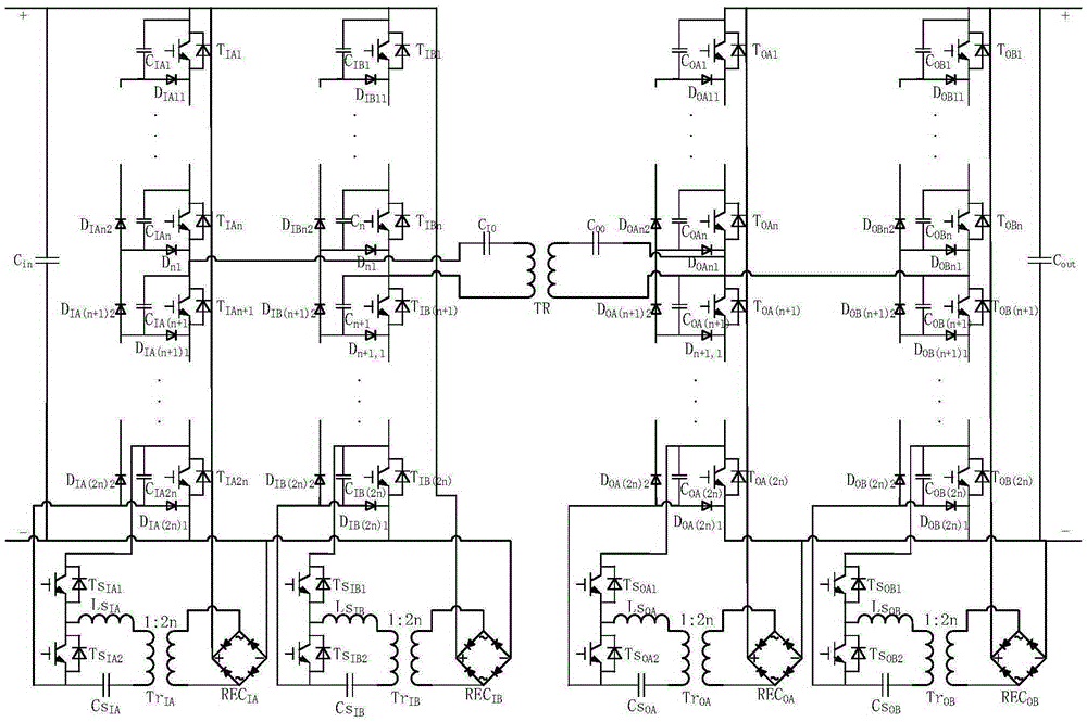
[0032] like Figure 4 As shown, in order to realize the bidirectional transformation of the DC voltage of the DC transformer, this embodiment also discloses a bidirectional diode clamp power switch series high-voltage DC transformer, which includes two bridge arm groups, which are respectively the I-side bridge arm group and the O-side bridge arm group, the single bridge arm group is composed of the above-mentioned unidirectional diode clamp power switch connected in series with the high-voltage DC transformer to remove the high-frequency transformer Tr, single-phase rectifier bridge REC, and DC blocking capacitor C 0 , Input side bus capacitance C in and output side bus capacitance C out And increase the high-frequency transformer TR, the input side bus capacitor C Iin and output side bus capacitance C Oout composition. The I-side bridge arm group and the O-side bridge arm group are connected through a high-frequency transformer TR, and the DC blocking capacitor C I0 One...


PUM


Abstract

The invention discloses a high-voltage direct-current transformer connected with a diode clamping power switch in series, belonging to the technical field of electrical and electronic applications. The high-voltage direct-current transformer connected with the diode clamping power switch in series can be applied to direct direct-current electric energy voltage grade transformation in a high-voltage high-power occasion, such as direct-current transmission. The invention discloses a high-voltage direct-current transformer connected with a unilateral diode clamping power switch in series; a topological structure included in the invention is used for enabling voltage between capacitors included in the topological structure to be balanced and enabling voltage between power switches to be balanced; and simultaneously, the topological structure is used respectively in combination with auxiliary circuits, such that voltage at two ends of the power switches included in the topological structure can be limited. To realize bidirectional transformation of direct-current voltage of the direct-current transformer, the invention further discloses a high-voltage direct-current transformer connected with a bidirectional diode clamping power switch in series; and the technical problem to be solved by the invention is to provide the high-voltage direct-current transformer connected with the diode clamping power switch in series, which can enable voltage at two ends of the serial power switches to be balanced, limit voltage at two ends of the power switches, and satisfy high-voltage high-power application.

Description

technical field [0001] The invention relates to a diode-clamped power switch connected in series with a high-voltage direct current transformer, in particular to a diode-clamped power switch connected in series with a high-voltage direct current transformer for direct current conversion, which can be applied to direct direct current electric energy voltage level conversion in high-voltage and high-power occasions such as direct current transmission, and belongs to electric power The field of electronic application technology. Background technique [0002] Compared with AC transmission, HVDC transmission has the characteristics of large transmission power capacity, small loss, long transmission distance, and good stability, which has broad application prospects. At present, the rectifier side and the inverter side of the HVDC transmission system still need a power frequency transformer with a large volume and a large mass to realize the connection with the AC power grid. DC ...

Claims


Application Information

Patent Timeline
Patent Type & Authority Applications(China)
IPC IPC(8): H02M3/335H02M7/487
CPCH02M3/3353H02M7/487
Inventor 高聪哲李星宇刘向东陈振
Owner BEIJING INSTITUTE OF TECHNOLOGYGY
Why Eureka
Try Eureka