
A Diode Clamp Power Switch Series High Voltage Inverter and Its Topological Structure

A technology of diode clamping and high-voltage inverters, which is applied in the direction of converting AC power input to DC power output, output power conversion devices, electrical components, etc. Problems such as voltage imbalance, to achieve the effect of increasing the number of components, good voltage clamping effect, increasing cost and complexity

Active Publication Date: 2018-09-21
BEIJING INSTITUTE OF TECHNOLOGYGY
View PDF4 Cites 0 Cited by
  • Summary
  • Abstract
  • Description
  • Claims
  • Application Information

AI Technical Summary

Problems solved by technology

Unsynchronized gate drive signals can cause voltage spikes and high quiescent voltages on devices that lag during turn-on, resulting in unbalanced voltage across power switches
The degree of asynchrony of the gate drive signal depends on the control circuit and the transmission line between the control circuit and the gate drive, so the degree of asynchrony is difficult to predict in advance

Method used


Image

  • A Diode Clamp Power Switch Series High Voltage Inverter and Its Topological Structure
  • A Diode Clamp Power Switch Series High Voltage Inverter and Its Topological Structure
  • A Diode Clamp Power Switch Series High Voltage Inverter and Its Topological Structure

Examples


Embodiment 1

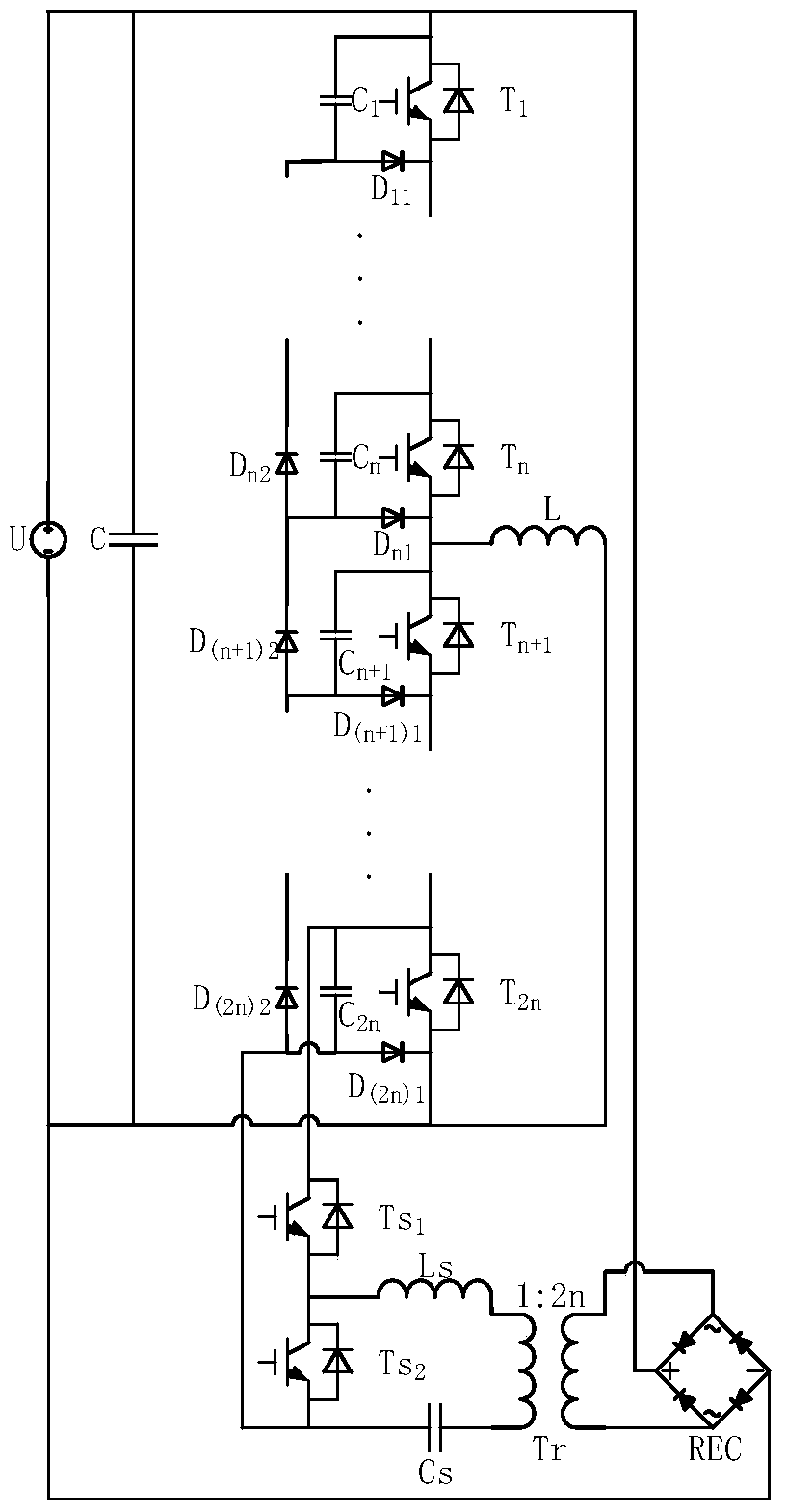
[0028] Embodiment 1: The number of diode-clamped power switch series voltage equalizing units required depends on the voltage level and power level of the working conditions. Take the use of 6 diode-clamped power switches connected in series as a voltage equalizing unit as an example for illustration.

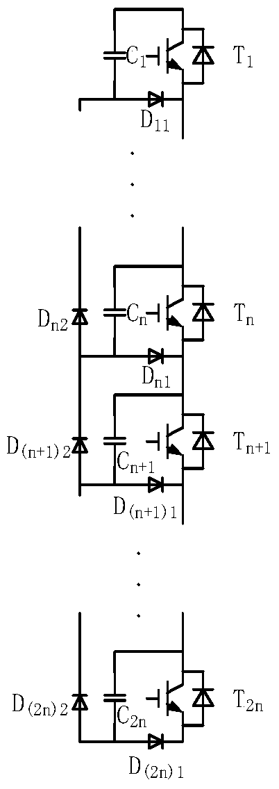
[0029] Such as Figure 4 As shown, the topology disclosed in this embodiment is used for a diode-clamped power switch series high-voltage inverter, including a power switch T i (1≤i≤6), clamping diode D i1 (1≤i≤6), clamp capacitor C i (1≤i≤6), freewheeling diode D i2 (2≤i≤6), auxiliary circuit power switch Ts 1 and Ts 2 , Auxiliary circuit freewheeling inductance Ls, auxiliary circuit blocking capacitor Cs, auxiliary circuit high-frequency transformer Tr (primary and secondary transformation ratio is 1:2n), auxiliary circuit single-phase rectifier bridge REC. power switch Ti (1≤i≤6) collector and clamp capacitor C i (1≤i≤6) connected to one end, the clamping capacitor C ...

Embodiment 2

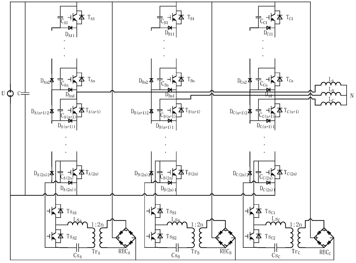
[0032] Embodiment 2: The number of diode-clamped power switch series voltage equalizing units required depends on the voltage level and power level of the working conditions. The single-phase diode-clamped power switch is connected in series with the high-voltage inverter, and 6 diode-clamped power switches are connected in series with the voltage equalizing unit. The three-phase diode-clamped power switch is connected in series with the high-voltage inverter, and 18 diode-clamped power switches are connected in series with the voltage-balancing unit. Take this as an example.

[0033] Such as Figure 6 As shown, a three-phase diode-clamped power switch series high-voltage inverter disclosed in this embodiment is a three-phase three-wire diode-clamped power switch series-connected high-voltage inverter, and the diode-clamped power switch series The high-voltage inverter is used as a single-phase diode-clamped power switch series high-voltage inverter, and the three-phase three...


PUM


Abstract

The invention discloses a diode clamp power switch series-connection high-voltage inverter and a topological structure applied to the diode clamp power switch series-connection high-voltage inverter and belongs to the technical field of power electronic application. The topological structure is used for enabling voltage balance among capacitors and voltage balance among power switches in the topological structure, and the voltage at two ends of each power switch in the topological structure can be limited when the topological structure is combined with an auxiliary circuit for use. The invention further discloses the diode clamp power switch series-connection high-voltage inverter and a three-phase diode clamp power switch series-connection high-voltage inverter which are implemented on the basis of the topological structure. The diode clamp power switch series-connection high-voltage inverter and the corresponding topological structure can realize two-end voltage balance of series-connection power switches, limit the voltage at two ends of each power switch and meet high-voltage high-power application.

Description

technical field [0001] The invention relates to a diode-clamped power switch series high-voltage inverter and a topology structure for the diode-clamped power switch series high-voltage inverter, in particular to a diode-clamped power switch series high-voltage inverter applied to high voltage and high power. Transformers, belonging to the field of power electronics application technology, Background technique [0002] High-voltage inverters can convert high-voltage and high-power direct current to alternating current, and are widely used in industrial production and daily life. With the continuous development of power electronics technology, the voltage level and power of the inverter continue to increase. The input voltage and power of the ordinary two-level high-voltage inverter are affected by the voltage level and overcurrent capability of the power switch used. limitations and cannot meet actual needs. [0003] The series power switch inverter is an important method ...

Claims


Application Information

Patent Timeline
Patent Type & Authority Patents(China)
IPC IPC(8): H02M7/487
CPCH02M7/487
Inventor 高聪哲李星宇刘向东陈振
Owner BEIJING INSTITUTE OF TECHNOLOGYGY
Learn More