Soil disinfection device

A soil disinfection and soil technology, applied to the device, application, chemistry, etc. of capturing or killing insects, can solve the problems of increasing body weight, heavy use, limited power supply of motors, etc., to achieve improved efficiency, environmentally friendly structure, and light structure Effect

Active Publication Date: 2015-05-06
上海光崎机械贸易有限公司
View PDF5 Cites 4 Cited by
  • Summary
  • Abstract
  • Description
  • Claims
  • Application Information

AI Technical Summary

Problems solved by technology

On the one hand, this kind of spraying equipment equipped with a motor is cumbersome to use. For the already hard-working operator, it will undoubtedly increase the burden on the body.
On the other hand, when this spray equipment equipped with a motor is used, the power supply of the motor is also very limited.
[0004] There is also a technology to provide power by installing a built-in battery pack, but the bulky battery pack itself increases the weight of the device
At the same time, if the used batteries cannot be discarded properly, it will cause new pollution to the environment, especially the soil.

Method used


Image

  • Soil disinfection device
  • Soil disinfection device
  • Soil disinfection device

Examples


Embodiment 1

[0049] The purpose of the present invention is achieved through the following technical solutions:

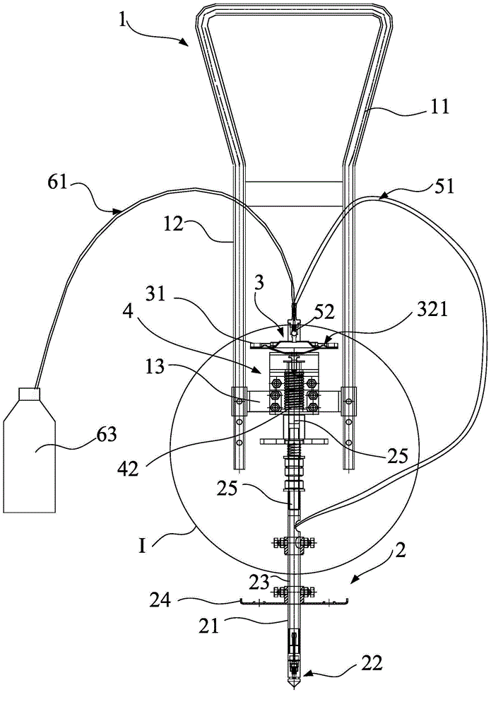
[0050] Such as Figure 1 to Figure 7 As shown, the present invention provides a soil disinfection device, which includes a handle body 1 and a spraying part 2 connected to the bottom of the handle body 1 .

[0051] The spraying part 2 includes a spraying rod 21 for inserting into the soil, and a mechanical power part is also provided between the handle body 1 and the spraying part 2 .

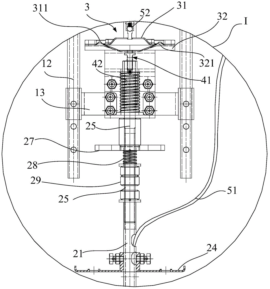
[0052] The mechanical power part includes: a sealed cavity 3 for storing liquid, and the sealed cavity 3 is located above the injection part 2; a liquid inlet part and a liquid outlet part, which are respectively interlocked with the sealed cavity 3 in one-way conduction . It also includes an elastic part 4 , which abuts against the bottom of the sealed cavity 3 and is located on the top of the injection part 2 .

[0053] The liquid in this technical solution refers to pesticides and the like...

Embodiment 2

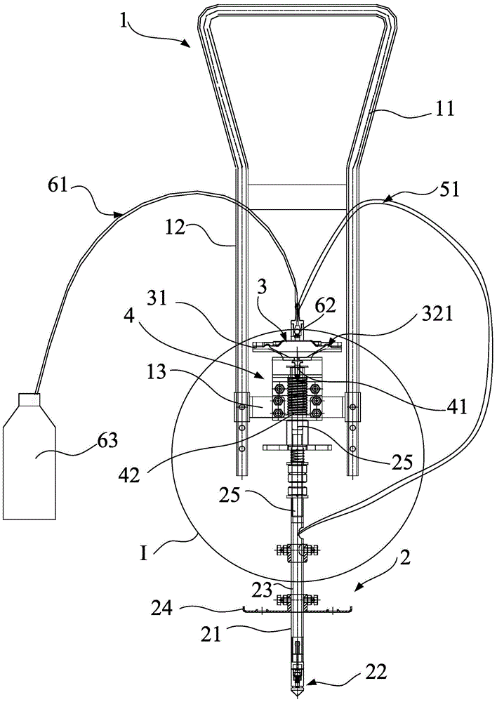
[0076] This embodiment is basically the same as Embodiment 1, except that the soil disinfection device in this embodiment also includes a limit stop plate 24 horizontally sleeved on the bottom of the spray rod.

[0077] Such as image 3 As shown, the stop plate 24 is located above the annular nozzle hole 22 . It is used to limit the soil insertion depth of the spray rod 21, that is, to ensure that the disinfectant is sprayed within the set soil depth. This ensures efficient soil disinfection.

[0078] Of course, in actual implementation, the limit stop plate 24 and the spray rod 21 can be movably sleeved, or can be fixedly connected to the spray rod.

[0079] Other parts of this embodiment are identical to Embodiment 1.

Embodiment 3

[0081] This embodiment is basically the same as Embodiment 1, except that the guide core in this embodiment can also be arranged on the bottom of the sealed cavity through a push pin. That is to say, an ejector pin is inserted on the top of the guide core, and then the pin head of the ejector pin abuts against the center of the bottom of the sealed cavity. In this way, the bottom of the sealed cavity can be stressed intensively, and the sealed cavity can be deformed more easily through the compression of the elastic member.

[0082] Other parts of this embodiment are identical to Embodiment 1.


PUM


Abstract

The invention discloses a soil disinfection device, which comprises a holding rod body and a spray part, wherein the spray part comprises a spray rod used for inserting into soil, a mechanical power part is also arranged between the holding rod body and the spray part and consists of a sealing cavity, a liquid inlet part and a liquid outlet part as well as elastic part, wherein the sealing cavity is positioned above the spray part and used for storing liquid; the liquid inlet part and the liquid outlet part are respectively interlocked and communicated with the sealing cavity in a one-way manner; the elastic part props against the bottom of the sealing cavity and is elastically connected with the top of the spray part; when the spray rod is inserted into the soil, the elastic part extrudes the sealing cavity, the liquid outlet part is communicated with the sealing cavity, so that liquid can be imported into the spray part for outward spraying; when the spray rod is pulled out from the soil, the sealing cavity is released from the elastic part, the liquid inlet part is communicated with the sealing cavity, so that liquid can flow in the sealing cavity. By adopting the soil disinfection device, not only does the structure be portable, but also the soil disinfection device is energy saving and environmentally friendly; in addition, the labor intensity can be greatly lightened, and the agricultural production efficiency can be improved.

Description

technical field [0001] The invention relates to the technical field of agricultural machinery, in particular to a device for disinfecting soil. Background technique [0002] As we all know, the quality of crop growth depends largely on the soil on which its growth depends. In order to adapt to the characteristics of crop growth, it is necessary to improve or improve the quality of the soil by injecting corresponding medicine into the soil. For example, in order to prevent insects, it is necessary to inject anti-insect agents for disinfection into the soil and the like. [0003] As a result, a device for spraying liquid into the soil has appeared on the market. However, the power of pumping or spraying of existing soil blasting machines is mostly provided by the motor equipped with the equipment itself. On the one hand, this kind of injection equipment equipped with a motor is cumbersome to use, and undoubtedly increases the burden on the operator who is already very hard....

Claims


Application Information

Patent Timeline
Patent Type & Authority Applications(China)
IPC IPC(8): A61L2/18A01M7/00
Inventor 高山恭生
Owner 上海光崎机械贸易有限公司
Why Eureka
Try Eureka