
A flatness compensation system and method for a compact field plane scanning frame

A plane scanning and compensation system technology, applied in general control systems, control/regulation systems, instruments, etc., can solve problems such as difficulty in ensuring compensation effects

Active Publication Date: 2017-03-22
BEIJING INST OF RADIO METROLOGY & MEASUREMENT
View PDF3 Cites 0 Cited by
  • Summary
  • Abstract
  • Description
  • Claims
  • Application Information

AI Technical Summary

Problems solved by technology

However, for the compact field plane scanning frame with large size, complex environment or long test process period, the actual situation of the scanning frame may change greatly from the current state of the calculated correction table with time or environmental changes, and the above method is difficult to guarantee the compensation effect

Method used


Image

  • A flatness compensation system and method for a compact field plane scanning frame
  • A flatness compensation system and method for a compact field plane scanning frame
  • A flatness compensation system and method for a compact field plane scanning frame

Examples


Embodiment Construction

[0045] In order to illustrate the present invention more clearly, the present invention will be further described below in conjunction with preferred embodiments and accompanying drawings. Similar parts in the figures are denoted by the same reference numerals. Those skilled in the art should understand that the content specifically described below is illustrative rather than restrictive, and should not limit the protection scope of the present invention.

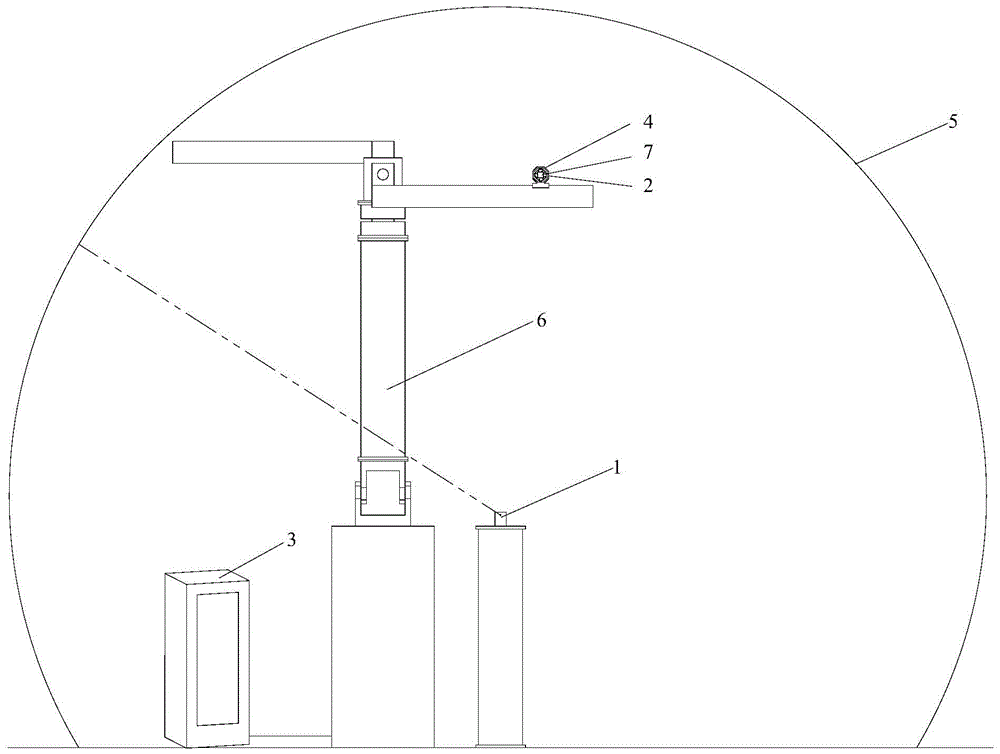
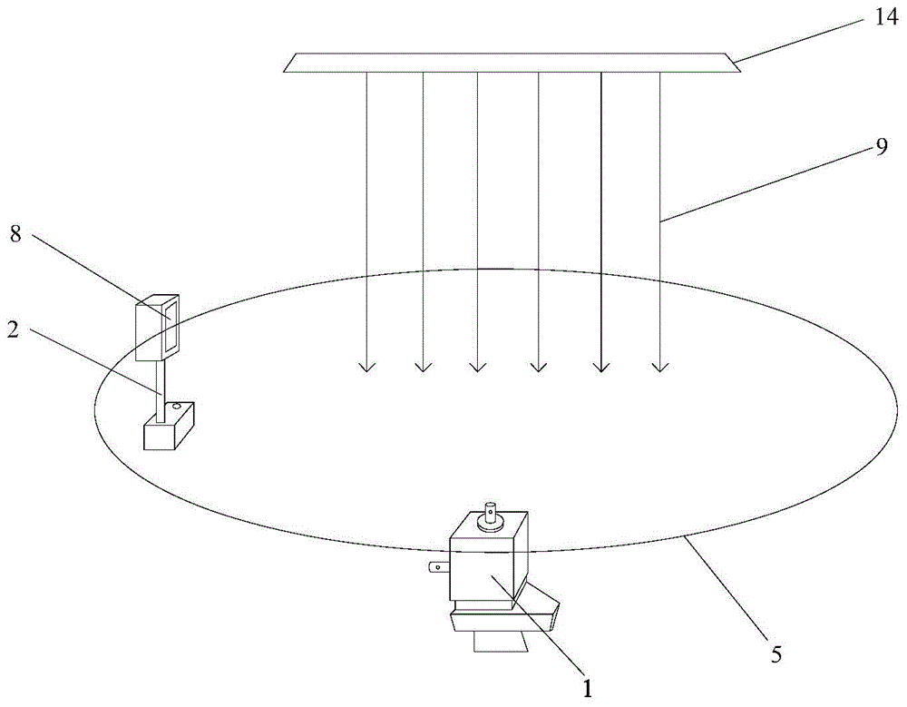
[0046] Such as figure 1 As shown, the flatness compensation system of the compact field plane scanning frame provided by this embodiment includes a laser plane emitting device 1, a position sensitive detector PSD2, a controller 3 and a servo compensator 4, and the connection relationship and working method are as follows:

[0047] The laser plane emitting device 1 is fixed on the ground, and it rotates itself so that the emitted laser beam generates a laser plane 5, and the laser plane 5 is used as a reference plane.

[0...


PUM


Abstract

The invention discloses system and method for compensating planeness of a compact field plane scanning frame. The system comprises a laser plane emitter for enabling emitted laser beams to form a laser plane by a self-rotating manner, a position-sensitive detector for detecting the position deviation of the laser plane and a zero position at the self-sensing area on real time and sending to a controller, the controller for generating driving current according to the position deviation to drive a servo compensator, and the servo compensator for driving the position-sensitive detector to jointly adjust the position to perform closed-loop control compensation for the planeness error of the scanning frame on real time. According to the technical scheme, the system has the advantages that the closed-loop control strategy is utilized to dynamically compensate the tail end of a scanning surface, and therefore, the problem of planeness error of the scanning plane caused by mechanical deviation due to the influences from mechanical processing, assembling precision, temperature, environmental vibration, gravity and other factors when the compact field plane scanning frame is in a complex environment or the testing cycle is relatively long, can be solved.

Description

technical field [0001] The invention relates to a real-time flatness compensation system. More specifically, it relates to a flatness compensation system and method for a compact field plane scanning frame. Background technique [0002] The flatness of the plane microwave formed by the squeezed field is an important index to evaluate the performance of the squeezed field, and the flatness of the squeezed field plane scanning frame is a special equipment for measuring this index. With the continuous development of science and technology, the area of ​​the microwave plane formed by the compact field is getting larger and higher, and the index is getting higher and higher, which directly puts forward higher requirements for the flatness index of the test plane formed by the scanning frame of the compact field plane. . [0003] The current compact field plane scanning frame generally uses the space scanning plane formed by the equipment through mechanical movement as the test ...

Claims


Application Information

Patent Timeline
Patent Type & Authority Patents(China)
IPC IPC(8): G05B19/404
CPCG05B19/404
Inventor 寇鹏孙祥溪吴翔任涛
Owner BEIJING INST OF RADIO METROLOGY & MEASUREMENT
Learn More