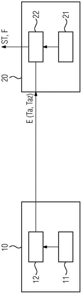
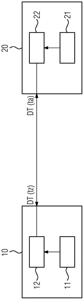
[0030] exist figure 1 A device with a signal generator 10 and a signal receiver 20 can be seen in FIG.
[0031] The signal generator 10 has a time reference 11 and a control device 12 which can be, for example, a programmable computing device. The signal receiver 20 has a time reference 21 and a control device 22 . The control device 22 can also be, for example, a programmable computing device.
[0032] If the control device 12 of the signal generator 10 determines that an event has occurred which should be reported to the signal receiver 20, the signal generator generates a corresponding event signal E(Ta, Taz). The event signal E(Ta, Taz) describes the event that occurred and specifies the event time, ie the event time Ta as the time reference 11 according to the signal generator 10 . Furthermore, the event signal E(Ta, Taz) gives the event time point Taz according to the time reference 21 of the signal receiver 20 . Because the control device 12 of the signal generator 10 is not connected to the time reference 21 of the signal receiver 20, the description of the event time point Taz is based on the fact that the control device 12 of the signal generator 10 generates the event signal E(Ta, Taz) or before Perform estimates.
[0033] After receiving the event signal E(Ta, Taz), the control device 22 of the signal receiver 20 re-evaluates the event time point, ie based on the time reference 11 of the signal generator 10 . The event time estimated by the signal receiver 20 (based on the time reference 11 of the signal generator 10 ) is denoted below by Ta′.
[0034] Considering the time point T az provided by the control device 12 of the signal generator 10 and estimated by the signal receiver 20 by means of the estimated path difference between the time reference 21 of the signal receiver 20 and the time reference 11 of the signal generator 10 Under the condition of the time deviation dTz(t) of , an estimation of the event time point Ta′ based on the time reference 11 of the signal generator 10 is performed.
[0035] The control device 22 of the signal receiver 20 then evaluates (in each case based on the time reference 11 of the signal generator 10 ) the event time Ta given in the event signal E(Ta, Taz) and its own estimated event time Ta′. Control device 22 , for example signal receiver 20 , forms the difference between time Ta and its own estimated time Ta′ and generates an error signal F when the difference reaches or exceeds a predetermined threshold value. If such an error signal F is generated or if the difference reaches or exceeds a predetermined threshold value, the event signal E(Ta, Taz) is preferably discarded and remains disregarded.
[0036] Otherwise, if the difference is below a predefined threshold, the control means 22 of the signal receiver 20 take this event signal E(Ta, Taz) into account and further process the reported event, for example based on its own time reference 21 in consideration of the event signal E( Ta, Taz) at the point in time Taz given or taking into account the point in time Ta based on the time reference 11 . The evaluation of the event signal E(Ta, Taz) can lead, for example, to the generation of the control signal ST.
[0037] Preferably, the signal generator 10 and the signal receiver 20 each estimate the time offset and the path difference between the two time references 11 and 21 themselves. This is exemplarily resorted to in the following Figures 2 to 6 explain.
[0038] exist figure 2 It can be seen from the figure that the signal generator 10 and the signal receiver 20 regularly or irregularly transmit time stamp messages DT(ta) and DT(tz) to each other.
[0039] The time stamp message DT(ta) is generated by the signal generator 10 and specifies the time according to the time reference 11 with respect to which the time stamp message DT(ta) is formed or transmitted. The time stamp message DT(tz) is generated by the signal receiver 20 and specifies the time stamp or time according to the time reference 21 with respect to which the time stamp message DT(tz) is formed or transmitted.
[0040] image 3 and Figure 4 It shows by way of example how the signal receiver 20 can evaluate the time-stamped telegram DT(ta) for estimating the path difference and the time-dependent time offset dTz(t).
[0041] The signal receiver 20 reads the time stamp ta contained in the time stamp telegram DT(ta) and forms the time difference tz-ta by subtracting the reception time point tz according to the time reference 21 and evaluates it with respect to time . This is exemplified by image 3 Shows. exist image 3 As can be seen in , the time difference values are evaluated on the basis of time windows, wherein each time window contains a plurality of time difference values tz-ta that follow one another in time.
[0042] in accordance with image 3 In the diagram of , time window F1 extends from time point t1 to time point t4, time window F2 extends from time point t2 to time point t5, time window F3 extends from time point t3 to time point t6, and time window F4 extends from time point Point t4 extends to time point t7. Temporally adjacent time windows preferably overlap each other by at least half the time window duration, according to image 3 Exactly 2/3 of the embodiments. The control device 22 of the signal receiver 20 determines a respective minimum time difference value for each time window F1 - F4 . exist image 3 In , the minimum time difference is represented by the reference symbol dtmin.
[0043] Figure 4 The time course of the minimum time difference dtmin(tz) with respect to the time tz of the time reference 21 of the signal receiver 20 is shown as an example. It can be seen that the minimum time difference dtmin(t) fluctuates around a straight drift characteristic line DK, the slope of which indicates the path difference between time references 11 and 21 . A straight drift characteristic line DK can be determined within the scope of an estimation method, for example based on the method of least squares.
[0044] By determining the slope of the drift characteristic line DK, the control device 22 of the signal receiver 20 can thus calculate or estimate the path difference between the time references 11 and 21 .
[0045] After determining the drift characteristic line DK and its slope or after determining the path difference between the time references 11 and 21, the minimum time difference dtmin(t ) drift correction or drift compensation. This corresponds intuitively to the tilt-drift characteristic line DK and follows Figure 4 The middle arrow direction P moves the minimum time difference dtmin(t). After drift correction or drift compensation, the absolute minimum time difference (allerkleinster Zeitdifferentenzwert) dtmin'(t0) can be found from the "minimum time difference (kleinster Zeitdifferentenzwert) dtmin(t)", which is for example related to the time Point t0 occurs. This absolute minimum time difference dtmin'(t0) can be interpreted as the time deviation dTz(t0) for the time point t0, and is used to determine the time deviation dTz( t).
[0046] The estimated time offset dTz can be used to process the incoming event signal E(Ta, Taz), as already combined with figure 1 explained.
[0047] Figure 5 and Image 6 It shows by way of example how the signal generator 10 can evaluate the time-stamped telegram DT(tz) for estimating the path difference and the time-dependent time offset dTa(t).
[0048] The signal generator 10 reads the time stamp tz contained in the time stamp telegram DT(tz) and forms a time difference value ta-tz by subtracting the respective reception time point ta according to the time reference 11 and compares it with respect to The time ta of the own time base is evaluated. This is exemplified by Figure 5 Shows.
[0049] exist Figure 5 As can be seen in , the time difference values are evaluated on the basis of time windows, wherein each time window contains a plurality of time difference values ta−tz that follow one another in time. in accordance with Figure 5 In the diagram of , time window F1 extends from time point t1 to time point t4, time window F2 extends from time point t2 to time point t5, time window F3 extends from time point t3 to time point t6, and time window F4 extends from time point Point t4 extends to time point t7. Temporally adjacent time windows preferably overlap each other by at least half the time window duration, according to Figure 5 Exactly 2/3 of the embodiments.
[0050] The control device 12 of the signal generator 10 determines a respective minimum time difference dtmin(t) for each time window F1 - F4 . Image 6 The time course of the minimum time difference dtmin(t) with respect to the time ta of the time reference 11 of the signal generator 10 is shown as an example. It can be seen that the minimum time difference dtmin(t) fluctuates around a straight drift characteristic line DK′, the slope of which gives the path difference between the time references 11 and 21 . A straight drift characteristic line DK′ can be determined within the scope of an estimation method, for example based on the method of least squares.
[0051] By determining the slope of the drift characteristic line DK', the control device 12 of the signal generator 10 can thus calculate or estimate the path difference between the time references 11 and 21, and use it to calculate or estimate for each time point at two Time-dependent time offset dTa(t) between time references 11 and 12 .
[0052] in accordance with Image 6 After determining the drift characteristic line DK' and its slope or after determining the path difference between the time references 11 and 21, the minimum time difference dtmin( t) drift correction or drift compensation. This corresponds intuitively to the tilt-drift characteristic line DK′ and follows Image 6 The middle arrow direction P moves the minimum time difference dtmin(t). After drift correction or drift compensation, the absolute minimum time difference dtmin'(t1) can be found from the "minimum time difference dtmin(t)". This absolute minimum time difference dtmin'(t1) can be interpreted as the time deviation dTa(t1) for the time point t1 and is used to determine the time deviation dTa( t).
[0053] The estimated time deviation dTa(t) can be used to form the event signal E(Ta, Taz) in order to calculate the time point Taz taking the path difference into account.
[0054] Figure 7 An exemplary embodiment of a rail vehicle 100 with a signal generator 10 and a signal receiver 20 is shown.
[0055] The signal generator 10 structurally corresponds to the figure 1 The signal generator 10 has a rail vehicle-side time reference 11 and a rail vehicle-side control device 12 . The signal generator 10 can, for example, generate as an event signal a position signal O(Ta, T az ) which gives the position of the rail vehicle 100 to the transponder 110, which gives the position point in time Ta according to the time reference 11 of the signal generator 10 and a correction value which indirectly or directly gives the time offset dTa estimated by the signal generator 10 between the time reference 21 of the signal receiver 20 and the time reference 11 of the signal generator 10 . The correction value can be transmitted, for example, in the form of the localization event time Taz estimated by the signal generator 10 from the time reference 21 of the signal receiver 20 .
[0056] The signal receiver 20 structurally corresponds to the figure 1 signal receiver 20 and has a rail vehicle-side time reference 21 and a rail vehicle-side control device 22 . The signal receiver 20 can generate an error signal F or a control signal ST for controlling the rail vehicle 100 taking into account the positioning signal O(Ta, Taz). Regarding the mode of operation of the signal generator 10 and the signal receiver 20 and regarding the cooperation between the signal generator 10 and the signal receiver 20 refer to the above in conjunction Figure 1 to Figure 6 implementation, which applies here accordingly.
[0057] Although the invention has been illustrated and described in detail by means of preferred embodiments, the invention is not limited to the disclosed examples, from which other variations can be deduced by a skilled person without departing from the scope of protection of the invention.