Liquid inner high-pressure crack initiation method for root of annular groove in surface of tube blanking

A technology of annular groove and internal high pressure, which is applied in the field of liquid internal high pressure crack initiation at the root of the surface annular groove, can solve the problems of unsatisfactory feeding efficiency for mass production and long service life of dynamic crack growth, so as to shorten the crack growth time and improve The effect of blanking efficiency

Active Publication Date: 2015-05-13
XI AN JIAOTONG UNIV
View PDF8 Cites 4 Cited by
  • Summary
  • Abstract
  • Description
  • Claims
  • Application Information

AI Technical Summary

Benefits of technology

This technology uses stress concentration for better crack growth performance by reducing load on the inside surface of pipes caused by external pressures greater than their maximum allowable design capacity.

Problems solved by technology

This patented technical problem addressed in this patent relates to improving the efficient and accurate fabricating of metallic tubular components like those found inside guns' cylinders. Traditional processes involve milling, drilling, deburring, machining, welding, brazing, die casting, and hot pressing techniques. These conventional ways require expensive tools and produce inferior results compared to innovations involving advanced technologies like thermoforming, injection forming, compression bonded lamination, cold working, electrostatic force sinter fusion, and ultrasonic wave sealing.

Method used


Image

  • Liquid inner high-pressure crack initiation method for root of annular groove in surface of tube blanking
  • Liquid inner high-pressure crack initiation method for root of annular groove in surface of tube blanking
  • Liquid inner high-pressure crack initiation method for root of annular groove in surface of tube blanking

Examples


Embodiment Construction

[0017] The present invention will be described in detail below in conjunction with the accompanying drawings.

[0018] A liquid internal high-pressure cracking method at the root of a surface annular groove for pipe blanking, comprising the following steps:

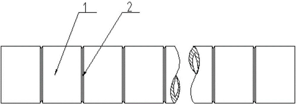
[0019] Step 1, before cracking, use a slotting machine to open an annular groove 2 on the outer surface of the metal pipe 1 according to the required blanking length;

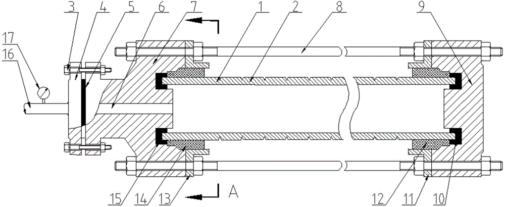
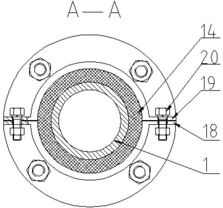
[0020] Step 2, when assembling, assemble the flange connector 7, the first clamp flange 13, the flat welding flange 4 and the liquid filling pipe 16 at one end of the metal pipe 1, and assemble the sealing head 9 and the second clamp flange at the other end 11. The two ends are respectively sealed by the first C-shaped sealing ring 15, the first stepped sealing sleeve 14, the second C-shaped sealing ring 10, and the second stepped sealing sleeve 12, and the two ends of the metal pipe 1 are connected by the first bolt 8 The flange joint 7 and the sealing h...


PUM


Abstract

Provided is a liquid inner high-pressure crack initiation method for the root of an annular groove in the surface of tube blanking. Before crack initiation, the annular groove is prefabricated in the surface of a metal tube, a flange connector and a charging tube are assembled at one end of the metal tube, a sealing head is assembled at the other end of the metal tube, the two ends of the metal tube are sealed through a C-shaped sealing ring and a step sealing sleeve respectively, and axial tensioning is carried out through bolts. In the crack initiation process, the metal tube is fast filled with emulsified liquid or hydraulic oil through the charging tube, the inner wall of the metal tube bears initial inner pressure, then high-pressure low-speed fluid is charged into the metal tube, inner high pressure is continuously applied to the inner wall of the metal tube, metal crystals at the root of the annular groove of the metal tube are made to slide and shift under the stress concentration effect, a persistent slip band is formed, and a microcrack group is formed finally. After crack initiation is finished, the metal tube is fed into a blanking machine to for segmented blanking. The stress concentration effect is utilized, the crack expansion time in the blanking process is effectively shortened, and blanking efficiency is improved.

Description


Claims


Application Information

Patent Timeline
Owner XI AN JIAOTONG UNIV
Why Eureka
Try Eureka