Power transmission system for vehicle and vehicle with same

A power transmission system and vehicle technology, which is applied to the arrangement of multiple different prime movers, transmission devices, power devices, etc. of a general power plant, and can solve problems such as fewer transmission modes, poor charging efficiency, charging mode, and single charging path , to achieve the effect of enriching the transmission mode

Active Publication Date: 2015-05-13
BYD CO LTD
View PDF4 Cites 13 Cited by
  • Summary
  • Abstract
  • Description
  • Claims
  • Application Information

AI Technical Summary

Problems solved by technology

[0003] However, in the related technologies known to the inventor, the power transmission system in a hybrid vehicle is generally complex in structure, with few transmission modes and low transmission efficiency.
For example, for most hybrid electric vehicles, the charging process is often realized during driving, the charging mode and charging path are relatively single, and the charging efficiency is poor

Method used


Image

  • Power transmission system for vehicle and vehicle with same
  • Power transmission system for vehicle and vehicle with same
  • Power transmission system for vehicle and vehicle with same

Examples


Embodiment 1

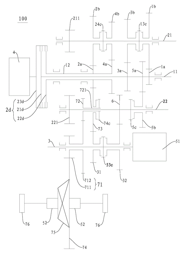
[0160] Such as figure 2 As shown, the engine 4 is connected with the input end 23d of the double clutch 2d, the first output end 21d of the double clutch 2d is connected with the first input shaft 11, the second output end 22d of the double clutch 2d is connected with the second input shaft 12, and the double clutch 2d is connected with the second input shaft 12. The input end 23d of the clutch 2d and the first output end 21d and the second output end 22d of the double clutch 2d can be in disconnected state at the same time, or the input end 23d of the double clutch 2d can be connected with the first output end 21d and the second output end 21d of the double clutch 2d. One of the two output terminals 22d is engaged, or the input terminal 23d of the dual clutch 2d can be simultaneously engaged with the first output terminal 21d and the second output terminal 22d of the dual clutch 2d.

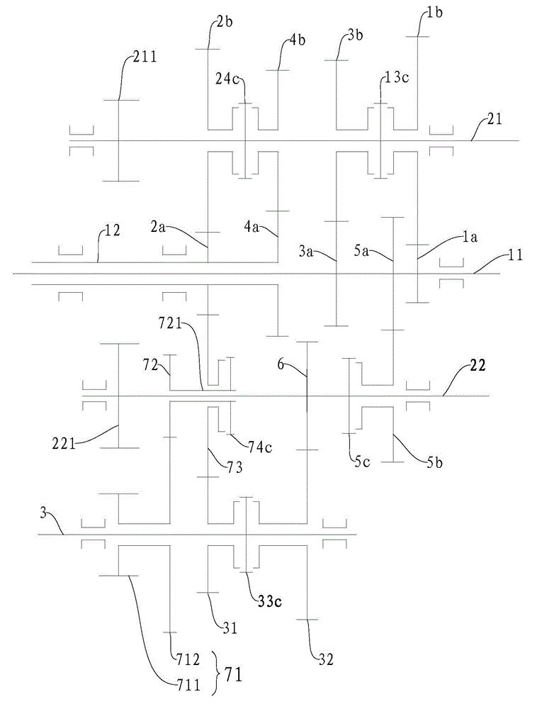
[0161] The second input shaft 12 is a hollow shaft structure, the first input shaft 11 is a...

Embodiment 2

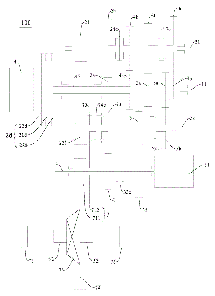
[0227] Such as image 3 As shown, the power transmission system 100 in this embodiment and figure 2 The main differences of the drivetrain 100 shown in are at the reverse intermediate gear 72, the idler intermediate gear 73 and the reverse synchronizer 74c. In this embodiment, the reverse intermediate gear 72 and the intermediate idler gear 73 are adjacent to the second output shaft 22, and the reverse synchronizer 74c is disposed on the intermediate idler gear 73 and is used to engage the reverse intermediate gear. 72. For the rest it can be used with figure 2 The power transmission system 100 in the embodiment is basically the same, and will not be repeated here.

Embodiment 3

[0229] Such as Figure 4 As shown, the power transmission system 100 in this embodiment and image 3 The main difference in the drivetrain 100 shown in is the configuration of the intermediate idler 73 . In this embodiment, the intermediate idler gear 73 is configured as a double gear, and has gear portions 731, 732, one of which gear portion 731 meshes with the second gear driving gear (that is, with the gear driving gear on the one of the input shafts). ), the other gear portion 732 meshes with the first gear 31 of the motor power shaft. For the rest it can be used with image 3 The power transmission system 100 in the embodiment is basically the same, and will not be repeated here.


PUM


Abstract

The invention discloses a power transmission system for a vehicle and the vehicle with the power transmission system. The power transmission system comprises an engine, a plurality of input shafts, a plurality of output shafts, a motor power shaft and a first motor-generator. The engine is arranged to be selectively connected with at least one of the input shafts, the output shafts and the input shafts are in transmission through gear pairs, the motor power shaft is arranged to be in linkage with one of the input shafts, the first motor-generator is arranged to be in linkage with the motor power shaft, and when the motor power shaft is in linkage with one of the input shafts, the first motor-generator can utilize at least part of power output by the engine for generating power when the vehicle runs and is parked. According to the power transmission system, the transmission mode is enriched, and parking charging, driving while charging of the engine and other work conditions can be achieved.

Description

technical field [0001] The invention relates to the technical field of vehicles, in particular to a power transmission system for a vehicle and a vehicle with the power transmission system. Background technique [0002] With the continuous consumption of energy, the development and utilization of new energy vehicles has gradually become a trend. As one of the new energy vehicles, a hybrid vehicle is driven by an engine and / or an electric motor, and has multiple modes, which can improve transmission efficiency and fuel economy. [0003] However, in the relevant technologies known to the inventor, the power transmission system in a hybrid vehicle generally has a complex structure, few transmission modes, and low transmission efficiency. For example, for most hybrid electric vehicles, the charging process is often implemented during driving, the charging mode and charging path are relatively single, and the charging efficiency is poor. Contents of the invention [0004] The...

Claims


Application Information

Patent Timeline
Patent Type & Authority Applications(China)
IPC IPC(8): B60K6/36
CPCF16H3/006
Inventor 杨冬生廉玉波张金涛罗红斌
Owner BYD CO LTD
Why Eureka
Try Eureka