CSP swing section wheel surface automatic lubrication device

A technology of automatic lubrication and swinging section, applied in the field of steel rolling equipment, can solve the problems of environmental pollution, adhesion of wheels and guide rails, accelerated wheel and guide rail damage, no supplementary grease, etc. rate effect

Active Publication Date: 2016-10-19
HBIS COMPANY LIMITED HANDAN BRANCH COMPANY
View PDF6 Cites 0 Cited by
  • Summary
  • Abstract
  • Description
  • Claims
  • Application Information

AI Technical Summary

Problems solved by technology

[0002] In order to improve the rolling rhythm of the rolling mill, the CSP production line is usually equipped with one rolling line, two continuous castings and two heating furnaces; the two heating furnaces realize the transfer of slabs between the two furnace bodies by setting swing sections, and finally the slabs are transferred Enter the furnace body before the rolling mill, enter the rolling mill for rolling; the swing of the swing section is realized by the wheels installed on the furnace body rotating on the guide rail, because the quality of the furnace body and the slab in the swing section is relatively large, and the wheels and guide rail Line contact, so the force at the contact point between the wheel and the guide rail is relatively large; if there is no lubricating grease on the contact surface between the wheel and the guide rail, the wear of the wheel and the guide rail will be greater, and the adhesion between the wheel and the guide rail may be caused, which will greatly accelerate the damage of the wheel and the guide rail
At present, the refueling system commonly used by domestic LCD companies is to smear grease on the surface of the guide rail. This method is used to lubricate the wheels and guide rails, but this method has many disadvantages: 1. The grease runs along the The loss on both sides of the wheel cannot be concentrated in the contact area between the wheel and the guide rail; 2. The loss of lubricating grease causes the oil film to have no replenishment of grease, and the oil film will rupture in a short time when the wheel is heavily loaded
3. The loss of grease causes waste of grease on both sides of the guide rail and causes environmental pollution

Method used


Image

  • CSP swing section wheel surface automatic lubrication device
  • CSP swing section wheel surface automatic lubrication device
  • CSP swing section wheel surface automatic lubrication device

Examples


Embodiment Construction

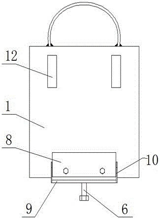
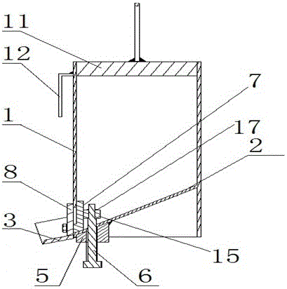
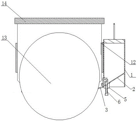
[0020] figure 1 , figure 2 , Figure 4 and Figure 5 It shows that the composition of the present invention includes a grease tank 1, an inner deflector 2, an outer deflector 3, a threaded lifting block 5, an adjustment screw 6, an inner oil adjustment plate 7 and an outer oil adjustment plate 8, and the inner deflector 2 is fixed on the inner wall of the grease tank 1, the angle between the inner deflector 2 and the bottom plate of the grease tank 1 is an acute angle, the side wall of the grease tank 1 is provided with a square oil hole 4, and the bottom of the oil hole 4 is located at the lower level of the inner deflector 2 At the junction of the edge and the side wall of the grease tank 1, the outer deflector 3 is composed of an outer deflector bottom plate 9 and two parallel outer deflector side plates 10, and one side of the outer deflector bottom plate 9 is connected to the grease tank 1 The bottom of the outer wall oil hole 4 is fixed, and the angle between the pla...


PUM


Abstract

The invention relates to an automatic lubricating device for the surface of a CSP swing segment wheel, and belongs to the technical field of steel rolling equipment. The automatic lubricating device is used for solving the technical problem that due to the fact that a wheel and a guide rail in the prior art cannot be lubricated automatically in good time, the wheel and the guide rail are abraded and damaged. According to the technical scheme, the automatic lubricating device comprises a grease box, an inner flow guide plate and an outer flow guide plate, the inner flow guide plate is fixed to the inner side wall of the grease box, an acute included angle is formed by the inner flow guide plate and a bottom plate of the grease box, an oil hole is formed in the side wall of the grease box, the bottom of the oil hole is located at the connecting position of the lower side of the inner flow guide plate and the side wall of the grease box, the outer flow guide plate is fixed to the position, at the bottom of the oil hole, of the outer side wall of the grease box, and an acute included angle is formed by the plane of the outer flow guide plate and the horizontal plane. The automatic lubricating device can effectively solve the problem that due to the fact that the wheel and the guide rail are abraded due to poor lubrication, the service life of the wheel and the guide rail is prolonged, and the action rate of a heating furnace is improved. The automatic lubricating device is suitable for automatic and timely lubrication of wheels and guide rails in relevant fields, and is wide in popularization prospect.

Description

technical field [0001] The invention relates to an automatic lubricating device for a wheel surface of a CSP swing section, belonging to the technical field of steel rolling equipment. Background technique [0002] In order to improve the rolling rhythm of the rolling mill, the CSP production line is usually equipped with one rolling line, two continuous castings and two heating furnaces; the two heating furnaces realize the transfer of slabs between the two furnace bodies by setting swing sections, and finally the slabs are transferred Enter the furnace body before the rolling mill, enter the rolling mill for rolling; the swing of the swing section is realized by the wheels installed on the furnace body rotating on the guide rail, because the quality of the furnace body and the slab in the swing section is relatively large, and the wheels and guide rail Line contact, so the force at the contact point between the wheel and the guide rail is relatively large; if there is no l...

Claims


Application Information

Patent Timeline
Patent Type & Authority Patents(China)
IPC IPC(8): B65G45/02
Inventor 邓建军韩社军吕德文孟凡毅樊国齐宋庆钊
Owner HBIS COMPANY LIMITED HANDAN BRANCH COMPANY
Why Eureka
Try Eureka