
A method and system for determining wave head time

A determination method, wave head technology, applied in the electrical field, can solve problems such as large error in results, difficulty in determining wave head time, etc.

Active Publication Date: 2017-05-31
STATE GRID CORP OF CHINA +1
View PDF3 Cites 0 Cited by
  • Summary
  • Abstract
  • Description
  • Claims
  • Application Information

AI Technical Summary

Problems solved by technology

[0004] However, the current method of determining the UHF signal wave head time is generally determined by human observation, and the power equipment in operation is generally in a strong noise environment, which is susceptible to corona discharge interference on overhead lines, and the UHF signal wave The head time is easy to be submerged in a strong noise environment, and it is not easy to determine, and human judgment will bring human factors, there are differences from person to person, and the result error is large

Method used


Image

  • A method and system for determining wave head time
  • A method and system for determining wave head time
  • A method and system for determining wave head time

Examples


Embodiment Construction

[0051] The core of the present invention is to provide a method for determining the wave head time, which can accurately determine the wave head time of the UHF signal, and is used to precisely locate the position of the partial discharge source of the electric equipment, thereby accurately judging the degree of danger of the partial discharge.

[0052] In order to make the purpose, technical solutions and advantages of the embodiments of the present invention clearer, the technical solutions in the embodiments of the present invention will be clearly and completely described below in conjunction with the drawings in the embodiments of the present invention. Obviously, the described embodiments It is a part of embodiments of the present invention, but not all embodiments. Based on the embodiments of the present invention, all other embodiments obtained by persons of ordinary skill in the art without making creative efforts belong to the protection scope of the present invention...


PUM


Abstract

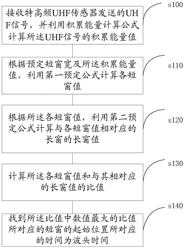
The invention discloses method and system for determining wave-head time. The method comprises the steps of receiving an UHF (Ultra High Frequency) signal sent by an UHF sensor; calculating the accumulated energy value of the UHF signal according to the accumulated energy calculation formula; calculating each short window value by a first preset formula according to the preset short window width and the accumulated energy value; calculating the long window value of a long window, corresponding to each short window value by the second preset formula; calculating the ratio of each short window value to the corresponding long window value; finding out the time corresponding to the starting position of the short window corresponding to the maximum ratio to be used as the wave-head time. With the adoption of the method, the wave-head time of the UHF signal can be accurately determined.

Description

technical field [0001] The invention relates to the field of electrical technology, in particular to a method and device for determining wave head time. Background technique [0002] Partial discharge detection of power equipment can find possible weak insulation aging and defects in the first time, which is of great practical significance to ensure the safe and reliable operation of equipment, and UHF (Ultra High Frequency) method as a possible The partial discharge detection method with live detection, high sensitivity and the ability to locate the discharge source has been widely used in the online monitoring and live detection of high-voltage equipment in domestic and foreign power companies. [0003] In order to better evaluate the insulation status of power equipment and formulate corresponding condition-based maintenance strategies, one of the prerequisites for the evaluation is to determine the location of partial discharge sources. Time difference positioning is a ...

Claims


Application Information

Patent Timeline
Patent Type & Authority Patents(China)
IPC IPC(8): G01R19/175G01R31/12
Inventor 邵先军何文林徐华刘浩军王文浩梅冰笑詹江杨
Owner STATE GRID CORP OF CHINA
Learn More