Spring delivery mechanism

A conveying mechanism and conveyor belt technology, applied in the direction of online nets, other household appliances, household appliances, etc., can solve the problems of affecting the work of the meshing machine and the overturning of springs.

Active Publication Date: 2017-06-06
宁波望春宏枫智能装备有限公司
View PDF1 Cites 0 Cited by
  • Summary
  • Abstract
  • Description
  • Claims
  • Application Information

AI Technical Summary

Problems solved by technology

[0003] Since the push plate is in contact with the small middle diameter portion of the spring, the push plate tends to push the spring down when pushing the spring toward the guide
This affects the follow-up work of the threading machine

Method used


Image

  • Spring delivery mechanism
  • Spring delivery mechanism
  • Spring delivery mechanism

Examples


Embodiment Construction

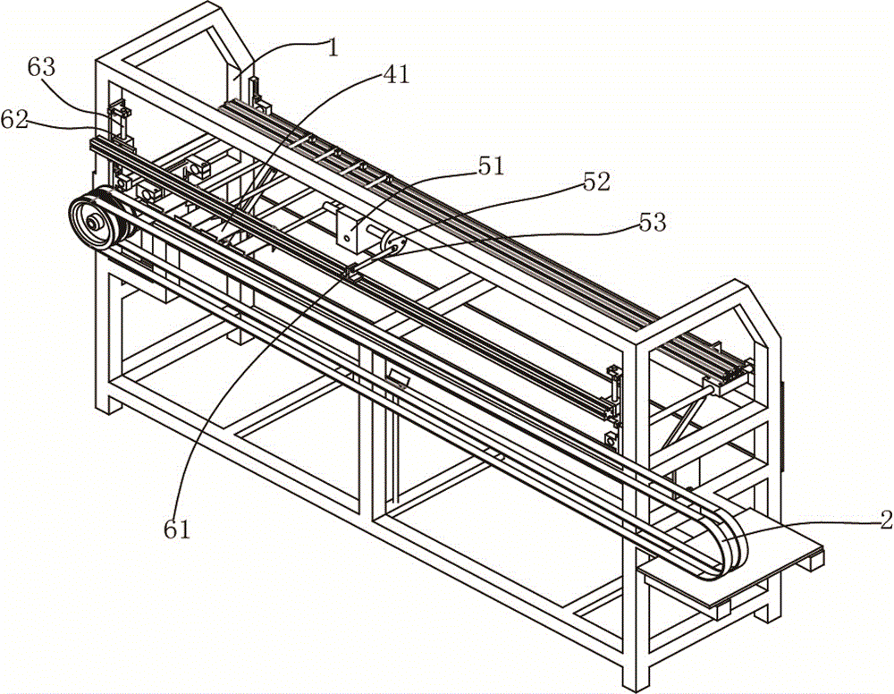
[0013] The present invention will be described in further detail below in conjunction with accompanying drawing and specific embodiment: see Figure 1 to Figure 3 , The spring conveying mechanism includes a frame 1 and a magnetic conveyor belt 2, and the spring is adsorbed on the conveyor belt 2. The horizontal direction of the frame 1 is provided with a push plate 3 and a first driving device that drives the push plate 3 to move. The push plate 3 is provided with a groove 31. When the push plate 3 pushes the spring 100 to move towards the screen threading machine , at least two sides of the groove 31 are in contact with the spring 100 .

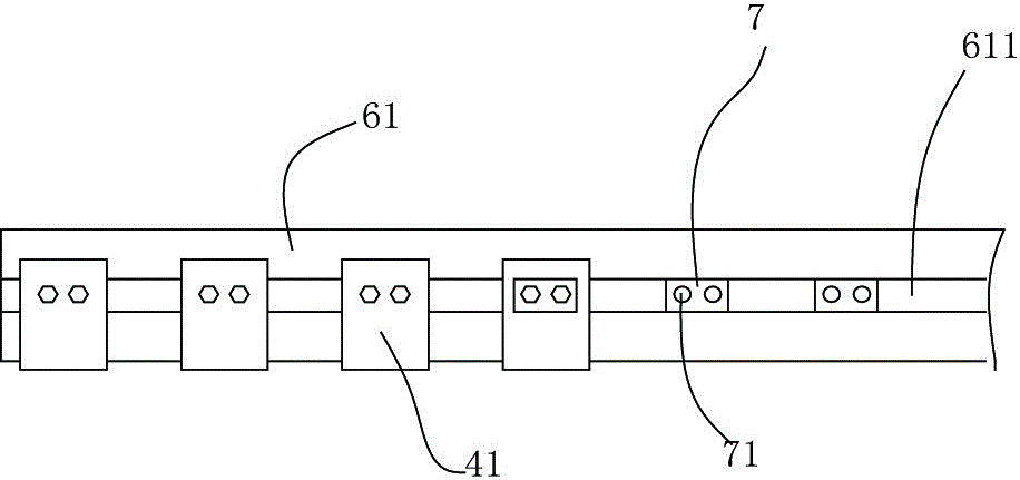
[0014] The vertical direction of frame 1 is provided with down-pressing mechanism, and described down-pressing mechanism comprises pressing plate 41 and the second driving device that drives pressing plate 41 to descend, and described second driving device comprises worm gear reduction mechanism 51, and described worm gear reduction mechanis...


PUM


Abstract

The invention provides a spring conveying mechanism. The spring conveying mechanism comprises a push plate and a first driving device used for driving the push plate to move. A groove is arranged on the push plate, when the push plate pushes a spring to move towards a net penetrating machine, at least two side faces of the groove make contact with the spring, the spring conveying mechanism further comprises a pressing mechanism, the pressing mechanism comprises pressing plates and a second driving device used for driving the pressing plates to descend, when the push plate pushes the spring to move towards the net penetrating machine, and the second driving device drives the pressing plates to descend to abut against the top of the spring.

Description

technical field [0001] The invention relates to a spring mattress processing equipment, in particular to a spring conveying mechanism for sending springs into a mesh threading machine. Background technique [0002] An application number of the patent applicant on January 29, 2013 is: CN201310033541.X, which discloses a spring guide device, including a push plate, a driving device for driving the push plate, and a guide piece. Grooves are arranged on the plate, at least two sides of the grooves are in contact with the smaller diameter part of the middle of the spring, the guide is fixed on the screen threading machine, and the guide has a guide surface, when the push plate When the spring is pushed to the threading machine, if the node under the spring is located in the interference area, the guide surface is in contact with the node at the bottom of the spring, and the guide surface is used to guide the spring The nodes of are pushed away from the interference region. Ensu...

Claims


Application Information

Patent Timeline
Patent Type & Authority Patents(China)
IPC IPC(8): B21F27/16B21F33/04
Inventor 苏卓洪刘锋
Owner 宁波望春宏枫智能装备有限公司
Why Eureka
Try Eureka