Foldable and convenient inverted-F-shaped retaining wall and design method thereof

A technology for retaining walls and retaining walls, applied in water conservancy projects, special data processing applications, artificial islands, etc., can solve problems such as affecting groundwater flow, large masonry work, waste of materials, etc., to improve safety and work efficiency, The effect of saving the use of resources and materials and reducing the labor force

Active Publication Date: 2021-03-23
TIBET UNIV
View PDF6 Cites 0 Cited by
  • Summary
  • Abstract
  • Description
  • Claims
  • Application Information

AI Technical Summary

Problems solved by technology

[0004] The disadvantages of the existing technology: (1) the most common gravity retaining wall is often limited by the bearing capacity when it is built on a weak foundation, and its material consumption is relatively large, which is a waste of material, which is not conducive to energy conservation and environmental protection; (2) Most of the existing retaining walls have a large volume and weight, a large amount of masonry, cannot be folded for transportation, and are disposable structures, which will be covered after use, affecting the flow of groundwater and affecting the environment; (3) when disasters occur If disasters cannot be controlled and mitigated in time, and retaining walls cannot be built quickly, it is easy to form natural disasters

Method used


Image

  • Foldable and convenient inverted-F-shaped retaining wall and design method thereof
  • Foldable and convenient inverted-F-shaped retaining wall and design method thereof
  • Foldable and convenient inverted-F-shaped retaining wall and design method thereof

Examples


Embodiment 1

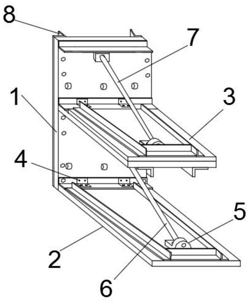
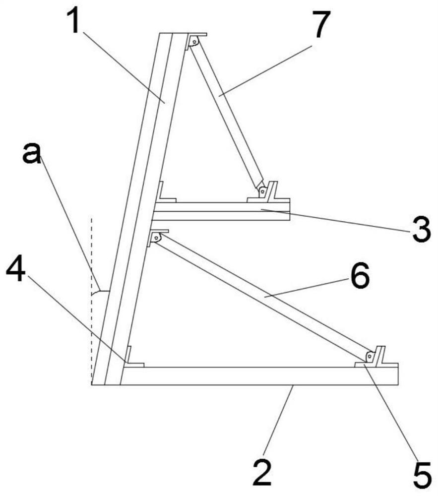
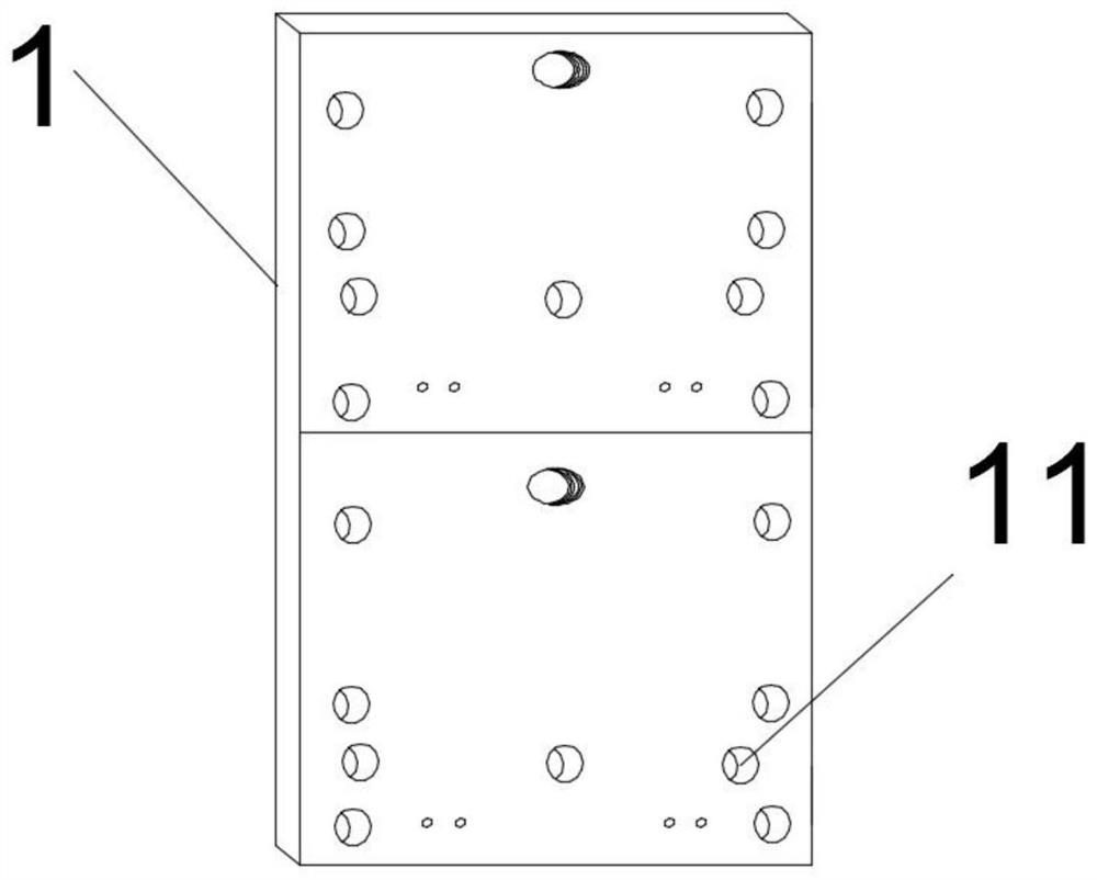
[0060] Embodiment 1: with reference to attached Figure 1-21 A foldable and convenient inverted F-shaped retaining wall is shown, including a baffle plate 1, a retaining wall base plate 2, and a retaining wall middle plate 3. The retaining wall base plate 2 is installed at the bottom of the retaining plate 1, and the retaining wall middle plate The plate 3 is installed in the middle of the baffle 1; and at least one fixed base 5 is arranged on the middle and top of the baffle 1, the bottom plate 2 of the baffle wall and the middle plate 3 of the baffle wall, and the middle part of the baffle 1 A support 6 is installed between the fixed base 5 and the fixed base 5 arranged on the bottom plate 2 of the retaining wall. The support 6 is used to provide tension to reduce the deformation of the lower part of the baffle 1 after being subjected to overturning soil pressure. A tie rod 7 is installed between the fixed base 5 at the top of the retaining wall and the fixed base 5 arranged...

Embodiment 2

[0070]Embodiment 2: The difference from Embodiment 1 is that usually in the disaster area, accumulations such as rockfall, collapse, and debris roll down the slope. Therefore, in order not to accumulate on the middle platform, we tilt the middle platform 3 of the retaining wall at an angle of Turn it down 10° so that the accumulation can slide smoothly on the floor, such as Figure 22 shown.

Embodiment 3

[0071] Embodiment 3: Different from Embodiment 2, in order to improve the anti-sliding stability of the inverted F-shaped retaining wall described in Embodiment 2, an anti-slip fastener 10 is designed, and this fastener is installed and welded on both sides of the retaining wall bottom plate 2, The anti-sliding fixture 10 is a 15cm long steel bar that forms an angle of 135° with the retaining wall bottom plate 2, thus effectively improving the anti-sliding stability, as Figure 23 shown.


PUM


Abstract

The invention discloses a foldable and convenient inverted-F-shaped retaining wall and a design method thereof. The foldable and convenient inverted-F-shaped retaining wall aims to quickly solve the problems that a road retaining wall is damaged due to aging or no retaining wall is provided, and geological disasters such as landslide, slump, debris flow, sand sliding slope and weathered material collapse are caused by temperature difference or a large amount of rainfall, and a road is damaged and blocked. According to the foldable and convenient inverted-F-shaped retaining wall, an existing retaining wall and the novel convenient inverted-F-shaped retaining wall are combined, and road disasters can be quickly solved by utilizing the stress structure characteristics and the use convenienceof the convenient inverted-F-shaped retaining wall; and the foldable and convenient inverted-F-shaped retaining wall is a novel inverted-F-shaped retaining wall which is composed of steel sheets and angle steel and can be folded by 80 degrees to be inclined, is convenient to transport, is easy to install, can efficiently prevent disasters, and improves traffic convenience and safety guarantee, andwhen the above disasters happen, due to accumulation of accumulated objects, the gravity of the retaining wall is increased, resistance is improved, the soil retaining effect is improved, the economic cost is saved, and resources are saved.

Description

technical field [0001] The invention belongs to the technical field of retaining wall design, in particular to a foldable and convenient inverted F-shaped retaining wall and a design method thereof. Background technique [0002] In the process of civil road construction, the retaining wall is a common support method, which is used to prevent the slope body or the side wall of the foundation pit from deforming or collapsing under the action of active earth pressure. According to its stiffness and Different displacement modes can be divided into three categories: rigid retaining wall, flexible retaining wall and temporary support; [0003] The supporting technical scheme of the retaining wall in the prior art is as follows: (1) most of the existing retaining walls maintain their balance by their own gravity, such as the most common gravity retaining, thin-walled retaining wall, U-shaped retaining wall in China. Retaining wall; (2) Retaining balanced retaining wall by tension,...

Claims


Application Information

Patent Timeline
Patent Type & Authority Applications(China)
IPC IPC(8): E02D29/02G06F30/13
CPCE02D29/0266E02D29/0225G06F30/13E02D2200/146E02D2600/20
Inventor 田荣燕旺久魏新晨孙威宇娄超华
Owner TIBET UNIV
Why Eureka
Try Eureka