Supercharge Your Innovation With Domain-Expert AI Agents!

Paying-off damping device of paying-off machine

A technology of damping device and pay-off machine, which is applied in the directions of transportation and packaging, transportation of filamentous materials, and processing of thin materials, can solve the problems of broken wires, difficult to control tension, fragile and conductors, etc., and achieves a simple overall structure, Improve the efficiency of disk replacement and the effect of long-lasting repeated service life

Inactive Publication Date: 2015-05-20
CHANGSHU ZHONGLIAN PHOTOELECTRICITY NEW STUFF
View PDF10 Cites 5 Cited by
  • Summary
  • Abstract
  • Description
  • Claims
  • Application Information

AI Technical Summary

Problems solved by technology

However, the pay-off reel often exhibits the following two technical problems during the pay-off process: one is that the line speed of the pay-off is difficult to control, and there are often extreme situations of tightness or looseness. Causes entangleme

Method used


Image

  • Paying-off damping device of paying-off machine

Examples


Embodiment 1

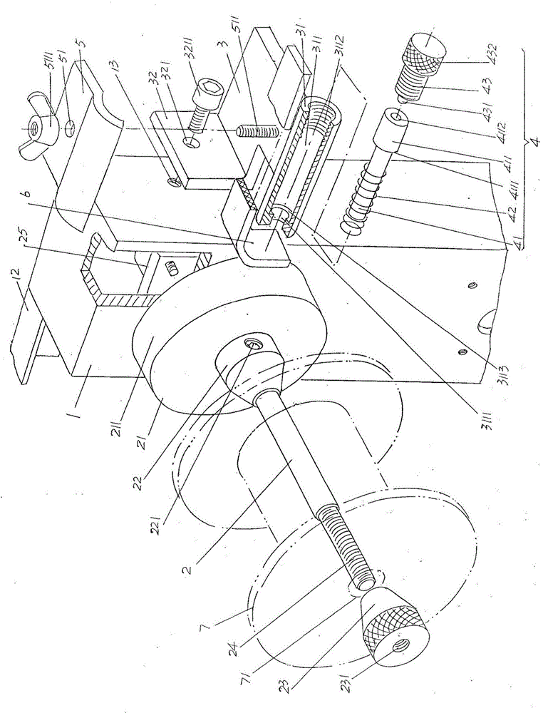
[0022] See figure 1 , provides a pay-off rack 1 belonging to the structural system of the pay-off machine; a pay-off shaft 2 for setting the pay-off reel 7, the rear end of the pay-off shaft 2 is rotatably supported on the pay-off rack through a bearing seat 25 1, and at the rear end of the pay-off shaft 2, a friction disc 21 and a pay-off disc rear support seat 22 are arranged. The position of the pay-off disc rear support seat 22 on the pay-off shaft 2 is located at the friction disc 21 and abuts against the friction disc 21, the front end of the pay-off shaft 2 is formed as a horizontal cantilever end, and is equipped with a front support seat 23 of the pay-off disc, and the aforementioned pay-off disc 7 is supported on the front and rear of the pay-off disc. Between the bearing seats 23,22.

[0023] According to professional knowledge, a plurality of pay-off shafts 2 can be set at intervals from top to bottom (also called bottom-up) in the height direction of the aforemen...

Embodiment 2

[0033] The figure is omitted, only the pay-off damping device of the present invention is transferred to the left side wall of the aforementioned pay-off rack 1, that is to say, the bracket 3 and the left side wall of the pay-off rack 1 are equivalent to the aforementioned screw holes 13. The hole is fixed. All the other are the same as the description to embodiment 1.


PUM


Abstract

The invention relates to a paying-off damping device of a paying-off machine and belongs to the technical field of auxiliary facilities for wire and cable processing. The paying-off machine comprises a paying-off frame and a paying-off shaft for a paying-off disc to be arranged, wherein the paying-off shaft is supported on the paying-off frame, a friction disc and a paying-off disc rear bearing seat are arranged at the rear end of the paying-off shaft, the paying-off disc rear bearing seat is located at the position, located on the front side of the friction disc and abutting against the friction disc, on the paying-off shaft, a horizontal suspension arm end is formed at the front end of the paying-off shaft, and a paying-off disc front bearing seat is arranged at the front end of the paying-off shaft in a matched mode. The paying-off damping device comprises a support, a damping piece adjusting mechanism and a damping piece clamping plate, wherein the support is fixed to the left side wall or the right side wall of the paying-off frame, a damping piece adjusting mechanism installation seat is formed on the front side of the support, the damping piece adjusting mechanism is arranged on the damping piece adjusting mechanism installation seat, and the damping piece clamping plate is arranged on the support. The interference influence on the paying-off disc is avoided, the disc replacing efficiency is improved, the durable and repeated service life of the paying-off disc is ensured, the overall structure is simple, operation is convenient, and the good maintenance-free effect is embodied.

Description

technical field [0001] The invention belongs to the technical field of auxiliary facilities for wire and cable processing, and in particular relates to a wire pay-off damping device for a wire pay-off machine. Background technique [0002] As known in the industry, in the wire and cable processing industry, according to the characteristics, uses and requirements of the corresponding process of the wire and cable products, it is necessary to process the conductor as the conductive core, such as drawing the conductor to make the conductor from thick to thin. Such as tinning the surface of copper conductors to form tinned copper conductors, another example is to form copper-clad aluminum conductors by plating copper on the surface of aluminum conductors, and annealing conductors, etc. [0003] Furthermore, as known in the industry, whether it is wire drawing, annealing, copper plating or tin plating of conductors, it is necessary to use a pay-off reel whose cross-sectional sha...

Claims


Application Information

Patent Timeline
IPC IPC(8): B65H59/38
Inventor 周家骝陆文龙许思祥朱贵钦
Owner CHANGSHU ZHONGLIAN PHOTOELECTRICITY NEW STUFF
Features
  • R&D
  • Intellectual Property
  • Life Sciences
  • Materials
  • Tech Scout
  • Unparalleled Data Quality
  • Higher Quality Content
  • 60% Fewer Hallucinations
Learn More