
Ceiling lamps

A technology for lamps and LED strips, applied in lighting and heating equipment, fixed lighting devices, semiconductor devices of light-emitting elements, etc., can solve the problems of poor lighting effect and small irradiation range of ceiling lamps, and achieve the effect of large irradiation area

Active Publication Date: 2019-04-12
OCEANKING DONGGUAN LIGHTING TECH +2
View PDF12 Cites 1 Cited by
  • Summary
  • Abstract
  • Description
  • Claims
  • Application Information

AI Technical Summary

Problems solved by technology

And the ceiling lamp has a small irradiation range and poor lighting effect

Method used


Image

  • Ceiling lamps
  • Ceiling lamps
  • Ceiling lamps

Examples


Embodiment Construction

[0031] In order to facilitate the understanding of the present invention, the present invention will be described more fully below with reference to the associated drawings. Preferred embodiments of the invention are shown in the accompanying drawings. However, the present invention can be embodied in many different forms and is not limited to the embodiments described herein. On the contrary, the purpose of providing these embodiments is to make the disclosure of the present invention more thorough and comprehensive.

[0032] It should be noted that when an element is referred to as being “fixed” to another element, it can be directly on the other element or there can also be an intervening element. When an element is referred to as being "connected to" another element, it can be directly connected to the other element or intervening elements may also be present. The terms "vertical," "horizontal," "left," "right," and similar expressions are used herein for purposes of ill...


PUM


Abstract

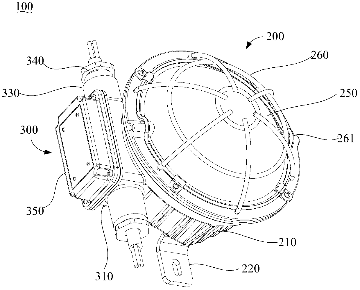
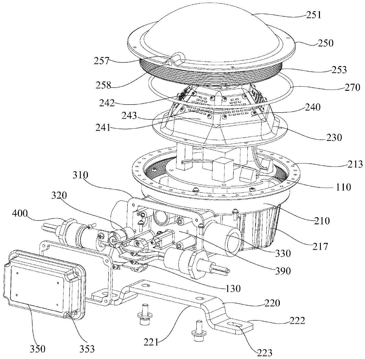
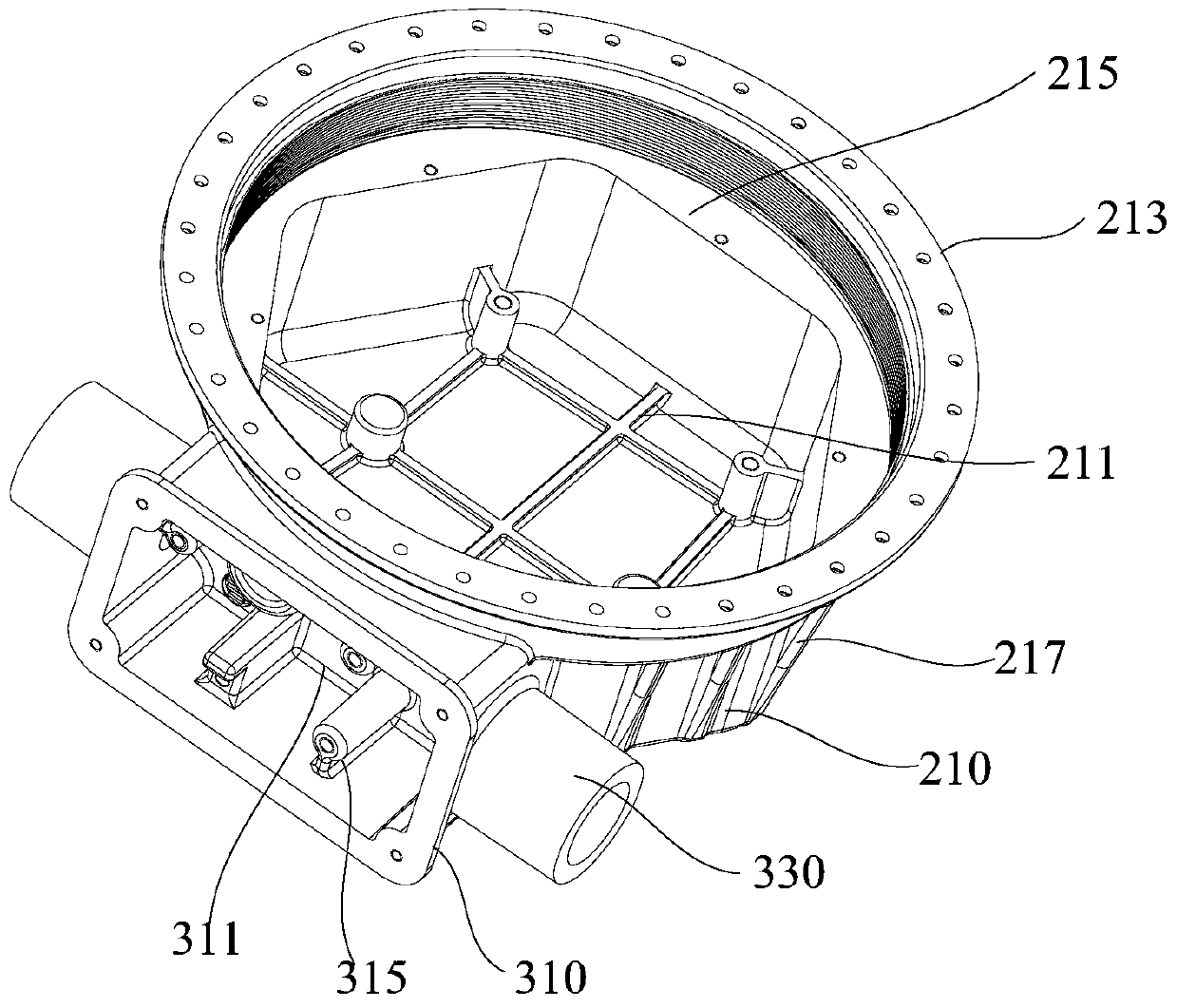
A ceiling light comprises a bottom shell, a transparent part, a wiring shell, a wire tube, an end cover and a wire protective casing. The bottom shell is used for containing drive elements, a heat dissipation cup is contained in the bottom shell, the outer side wall of the heat dissipation cup is provided with a plurality of installation platforms which are in isosceles trapezoid shapes, and the installation platforms are used for installing LED light bars. The transparent part is detachably connected with the open end of the bottom shell, a light source cavity is formed by the transparent part and the heat dissipation cup in an enclosure mode, and the transparent part comprises an arc-shaped transparent cover and an annular connecting part. The connecting part is arranged on the concave surface of the transparent cover, the inner side wall of the connecting part is provided with a plurality of transparent convex ribs which are arranged at intervals, the extension direction of the transparent convex ribs are parallel to the axial direction of the connecting part, the connecting part is provided with external threads, and the transparent part is connected with the bottom shell in a threaded mode. Light rays projected to the transparent convex ribs are finally transmitted from the transparent part through the refraction and reflection of the transparent convex ribs. According to the ceiling light, the light rays are dispersed uniformly, and the anti-dazzle effect can be achieved; even though the ceiling light is installed on a lower position, the harm to human eyes does not exist.

Description

technical field [0001] The invention relates to a lamp, in particular to a ceiling lamp. Background technique [0002] Ceiling lamps are used indoors. When installed, the installation surface of the lamp body is close to the ceiling, and are used to provide lighting fixtures for indoor ambient illumination. Ceiling luminaires are used to provide indoor ambient illumination. Due to the limited indoor height, when the light intensity of ceiling lamps is high, it is easy to make people feel dizzy in this environment for a long time. Moreover, the irradiation range of the ceiling lamp is small, and the lighting effect is poor. Contents of the invention [0003] Based on this, it is necessary to provide a ceiling lamp that has a large irradiation range and can prevent people from being dizzy. [0004] A ceiling lamp, comprising: [0005] It is a bottom shell with a cylindrical structure with one end open and one end closed, and the opening of the bottom shell is a light out...

Claims


Application Information

Patent Timeline
Patent Type & Authority Patents(China)
IPC IPC(8): F21S8/04F21V5/08F21V17/12F21V29/503F21V29/74F21Y115/10
CPCF21S8/043F21V5/08F21V17/12F21Y2101/00F21Y2107/40F21Y2115/10
Inventor 周明杰杨强
Owner OCEANKING DONGGUAN LIGHTING TECH
Learn More