Hydraulic control block with valve discs

A technology of control block and valve plate, applied in the direction of valve details, valve device, valve shell structure, etc., can solve the problem of high cost

Inactive Publication Date: 2015-05-27
ROBERT BOSCH GMBH
View PDF9 Cites 0 Cited by
  • Summary
  • Abstract
  • Description
  • Claims
  • Application Information

AI Technical Summary

Problems solved by technology

Since a screw is provided in all four corners of the two mutually resting valve plates, th

Method used


Image

  • Hydraulic control block with valve discs
  • Hydraulic control block with valve discs
  • Hydraulic control block with valve discs

Examples


Embodiment Construction

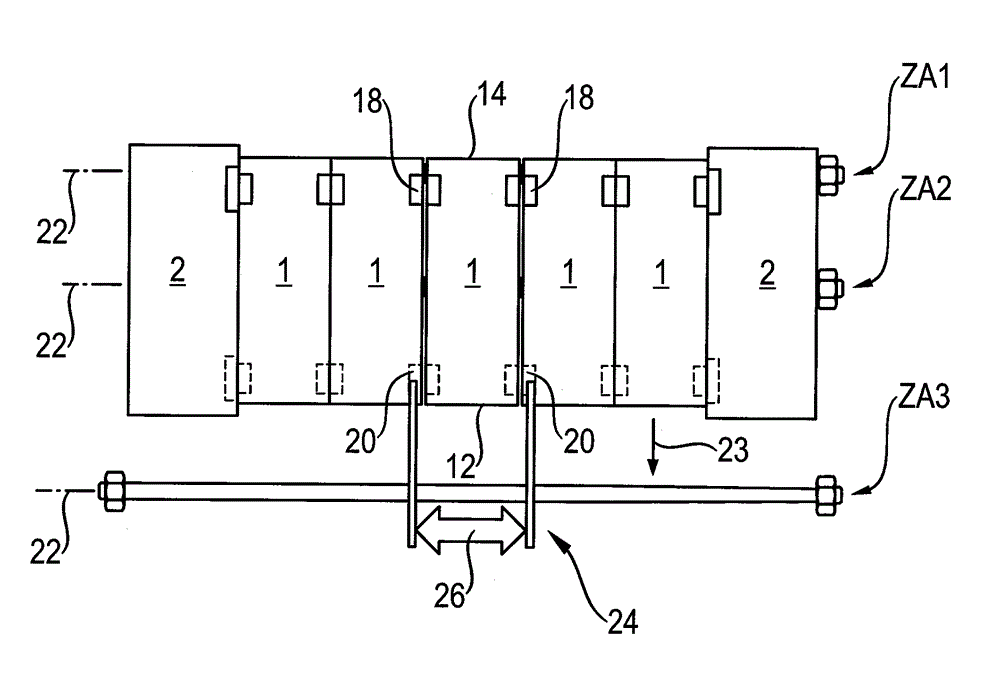
[0042] figure 1 A top view of a first embodiment of a control block according to the invention is shown. The control block has five valve plates 1 which are clamped together between a connecting plate 2 on the one hand and an end plate 4 on the other hand. Three tie rods ZA1 , ZA2 , ZA3 are used for this, each consisting of a rod-shaped body extending transversely through the valve plate 1 and the plates 2 , 4 and two nuts.

[0043] figure 2 shows the basis figure 1Side view of the middle valve section of the control block. Here, three tie rods ZA1 , ZA2 , ZA3 are shown in section. They are accommodated in corresponding recesses 6 , 8 , 9 . More precisely, in each valve section 1 in its figure 2 and on the outer side 10 of the lower part in the installation position, the lower approximately U-shaped recess 9 is drawn out, while the front U-shaped recess 8 is drawn out on the outer side 12 of the front part and on the rear part Draw out the U-shaped notch 6 of rear por...


PUM


Abstract

Disclosed is a hydraulic control block with a plurality of individual valve discs, which are clamped between a connection plate and an end plate by tie rods. The tie rods are releasable, whereby a middle valve disc can be removed without the control block has to be detached. According to a first scheme, the control block has four pull bars, two of the pull rods form a slide rail for vertically pulling out a value disc. The pulling can be in an upward or forward manner. The other two of the tie rods form a rear stopper or a lower support under the installation state of the valve discs. According to a second scheme, the control block has three pull rods, the rear pull rod forms a swing support for the valve discs and particularly for the valve discs to be detached, so that the valve discs can swing upwards after a front pull rod is taken out. The lower pull rod forms a support of the valve discs.

Description

technical field [0001] The invention relates to a hydraulic control block according to the preamble of claim 1 with a plurality of modularly combined valve plates. Hydraulic valves include such valve segments, which are used, for example, to supply and control individual hydraulic consumers of a mobile working machine. In this case, the individual substantially rectangular parallelepiped valve plates that bear against one another are clamped between a connecting plate and an end plate or a final valve plate. A non-positive and sealing fit between the valve plates is particularly important when the valve plates form a through transverse channel, such as a tank channel. Background technique [0002] DE 198 29 530 A1 shows a control block whose valve plates are pressed together via three screws. In this case, the bolts run through corresponding through-openings of all valve plates. [0003] A disadvantage of such a control block is the considerable assembly effort required t...

Claims


Application Information

Patent Timeline
IPC IPC(8): F15B13/02
CPCF16K27/003F15B13/0821F15B13/0839F16K27/00F15B13/08
Inventor P. 汉特克S. 克纳佩尔
Owner ROBERT BOSCH GMBH
Why Eureka
Try Eureka