
P2P connecting method, server, terminal and communication system

A P2P connection and server technology, applied in the communication field, can solve the problems of inability to select, decrease in system utilization, and inability to select other user terminals, etc.

Inactive Publication Date: 2015-05-27
LETV INFORMATION TECH BEIJING
View PDF5 Cites 2 Cited by
  • Summary
  • Abstract
  • Description
  • Claims
  • Application Information

AI Technical Summary

Problems solved by technology

At present, the server only plays an auxiliary role in the P2P-based streaming media transmission system architecture. The server selects other user terminals for the user terminal to establish a P2P connection, but when the server selects other user terminals for the user terminal to establish a P2P connection , the selection is made randomly without certain rules, so that the user terminal cannot select the most suitable other user terminal for establishing a P2P connection, which reduces the system utilization
[0006] To sum up, the current streaming media transmission system based on the P2P mode does not fundamentally solve the problems existing in the service mode of the traditional C / S mode. When the server selects other user terminals for establishing a P2P connection for the user terminal, This selection is performed randomly, and it is impossible to select other user terminals most suitable for establishing a P2P connection for this user terminal, so that information exchange and data resource sharing between user terminals cannot be carried out well, thereby making the network redundant. The remaining data increases, the load on the server increases, the system cost is high, and the utilization rate is low

Method used


Image

  • P2P connecting method, server, terminal and communication system
  • P2P connecting method, server, terminal and communication system
  • P2P connecting method, server, terminal and communication system

Examples


Embodiment Construction

[0082] The present invention provides a P2P connection method, a P2P connection server, a P2P connection terminal and a communication system, which are used to enable the server to better select other user terminals for the user terminal to establish a P2P connection, so as to reach the user The purpose of sharing data resources between terminals is to reduce system costs, improve system utilization, and increase data transmission rates.

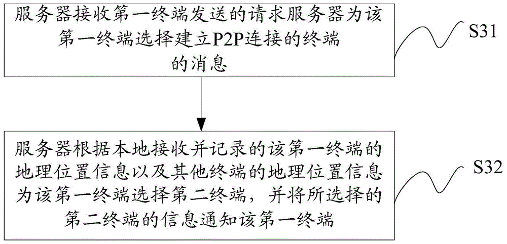
[0083] like image 3 As shown, on the server side, the embodiment of the present invention provides a P2P connection method, the method comprising:

[0084] S31. The server receives a message from the first terminal requesting the server to select a terminal for establishing a P2P connection for the first terminal;

[0085] S32. The server selects a second terminal for the first terminal according to the geographical position information of the first terminal received and recorded locally and the geographical position information of other t...


PUM


Abstract

The invention relates to a P2P connecting method, a P2P connecting server, a P2P connecting terminal and a communication system, for enabling a server to relatively well select other user terminals for establishing P2P connection for a user terminal, thereby achieving the purpose of data resource sharing of user terminals, reducing the system cost, increasing the system utilization rate and increasing data transmission velocity. The P2P connecting method comprises the following steps: receiving a message transmitted from a first terminal for requesting a server to select terminals for establishing P2P connection for the first terminal through the server; selecting a second terminal for the first terminal according to locally received and recoded geographical location information of the first terminal, and geographical location information of other terminals, and notifying the first terminal of the selected information of the second terminal.

Description

technical field [0001] The present invention relates to the communication field, in particular to a P2P connection method, a P2P connection server, a P2P connection terminal and a communication system. Background technique [0002] With the rapid development of the Internet and the increasing demand of users for multimedia information, especially when the number of users is gradually increasing, the traditional client / server (Client / Server, C / S) service model has gradually been unable to meet the needs of user terminals. For the need to obtain media information. [0003] like figure 1 As shown, the system architecture of the traditional C / S mode consists of three parts: an Internet Protocol Control (IPC) site, a server, and a user terminal, wherein each user terminal establishes a separate communication channel with the server, and the user terminal passes through the server. Obtain data resources from the IPC site. Therefore, when the number of user terminals increases s...

Claims


Application Information

Patent Timeline
IPC IPC(8): H04L29/08
CPCH04L67/104H04L67/1095H04L67/141H04L51/224H04L67/52
Inventor 李茗张海赵瑞前马宙李卓
Owner LETV INFORMATION TECH BEIJING
Learn More