
Suspensible scanner

A technology for scanners and casings, applied in the field of scanners, can solve the problems of not being able to hang on the wall for use, and not being able to make full use of the space

Inactive Publication Date: 2015-05-27
XIAN YUNYANG NETWORK TECH
View PDF0 Cites 0 Cited by
  • Summary
  • Abstract
  • Description
  • Claims
  • Application Information

AI Technical Summary

Problems solved by technology

[0003] The purpose of the present invention is to overcome the problem that the existing scanners can only be used on the desktop and cannot be hung on the wall, so that the space cannot be fully utilized

Method used


Image

  • Suspensible scanner
  • Suspensible scanner
  • Suspensible scanner

Examples


Embodiment 1

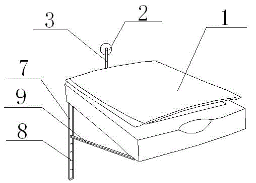
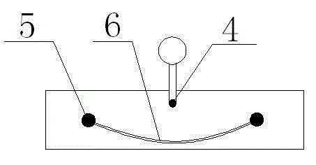
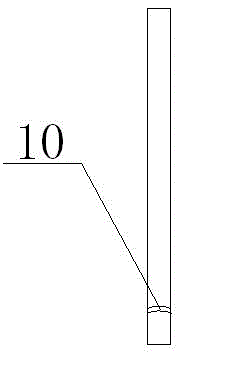
[0016] In order to overcome the defect that the existing scanners can only be used on the desktop and cannot be hung on the wall, so that the space cannot be fully utilized, the present invention provides a scanner such as figure 1 , figure 2 and image 3 The shown suspendable scanner includes a scanner housing 1, a suction cup 2 is connected to the back of the scanner housing 1, and a connecting rod 3 is fixed on the suction cup 2, and the scanner housing 1 The back is provided with a fixing device 4, the fixing device 4 is provided with a rotating shaft, the connecting rod 3 is connected to the rotating shaft in rotation, the left and right ends of the back of the scanner housing 1 are provided with screws 5, and the two Metal wires 6 are fixedly connected between the two screws 5, and two vertical first support rods 7 are fixedly connected to the left and right sides of the rear end of the bottom surface of the scanner housing 1, and the first support rods 7 are provided ...

Embodiment 2

[0019] On the basis of Embodiment 1, the connecting rod 3 is made of rubber material. When the suction cup 2 is not used for suspension, the suction cup 2 can be rotated and adsorbed on the scanner housing 1, so as to prevent the suction surface of the suction cup 2 from being contaminated with dust and affecting Adsorption effect: the first support rod 7 is a cavity structure, and the distance between the arc-shaped groove 10 and the bottom end of the second support rod 9 is consistent with the cavity depth of the first support rod 7, and the first support rod 7 and The second support rod 9 is fully fastened and fixed securely; the second support rod 9 is a sleeve-type retractable structure, which can make the scanner tilt at a suitable angle to facilitate people's work needs.


PUM


Abstract

The invention particularly provides a suspensible scanner which comprises a scanner housing, wherein a sucking disc is connected to the back of the scanner housing; a connecting rod is fixedly arranged on the sucking disc; a fixing device is arranged at the back of the scanner housing; a rotary shaft is arranged on the fixing device; the connecting rod is rotatably connected with the rotary shaft; screws are arranged at the left and right ends of the back of the scanner housing; a metal wire is fixedly connected between the two screws; two vertical first supporting rods are fixedly connected to the left and right sides at the rear end on the bottom face of the scanner housing; an arc-shaped bump is formed in each of the first supporting rods; two second supporting rods are movably connected to the left and right sides at the front end on the bottom face of the scanner housing; an arc-shaped groove matched with the arc-shaped bump is formed in a movable end of each of the second supporting rods. A suspending and supporting device is arranged on the scanner, so that the scanner can be suspended on the wall space to be used, and therefore, the work space of an office room is fully utilized.

Description

technical field [0001] The invention relates to a suspendable scanner. Background technique [0002] Scanners that exist on the market now generally can only be placed on the desktop and occupy the desktop work space of the desk, making the desktop crowded and messy, which brings inconvenience to people's work; at the same time, the space above the desk cannot be fully utilized and wastes office space. Contents of the invention [0003] The purpose of the present invention is to overcome the problem that the existing scanner can only be used on the desktop and cannot be hung on the wall, so that the space cannot be fully utilized. [0004] For this reason, the present invention provides a kind of suspendable scanner, comprises scanner shell, and described scanner shell back is connected with suction cup, and described suction cup is fixed with connecting rod, and described scanner shell The back is provided with a fixing device, the fixing device is provided with a rotat...

Claims


Application Information

Patent Timeline
Patent Type & Authority Applications(China)
IPC IPC(8): H04N1/04
CPCH04N1/04
Inventor 李宇
Owner XIAN YUNYANG NETWORK TECH
Learn More