
Automatic welding clamp for steel box bridge engineering

An automatic welding and bridge engineering technology, applied in the direction of manufacturing tools, welding equipment, auxiliary welding equipment, etc., can solve the problems of poor welding consistency, affecting product accuracy, and low operating efficiency

Pending Publication Date: 2022-01-11
江苏杰瑞信息科技有限公司
View PDF0 Cites 0 Cited by
  • Summary
  • Abstract
  • Description
  • Claims
  • Application Information

AI Technical Summary

Problems solved by technology

[0005] At present, the assembly of guardrail columns is completed manually. During the assembly process, temporary molds are used for positioning welding. The work efficiency is low and the welding consistency is poor. Low, unstable welding quality, large welding deformation, affecting product accuracy

Method used


Image

  • Automatic welding clamp for steel box bridge engineering
  • Automatic welding clamp for steel box bridge engineering
  • Automatic welding clamp for steel box bridge engineering

Examples


Embodiment 1

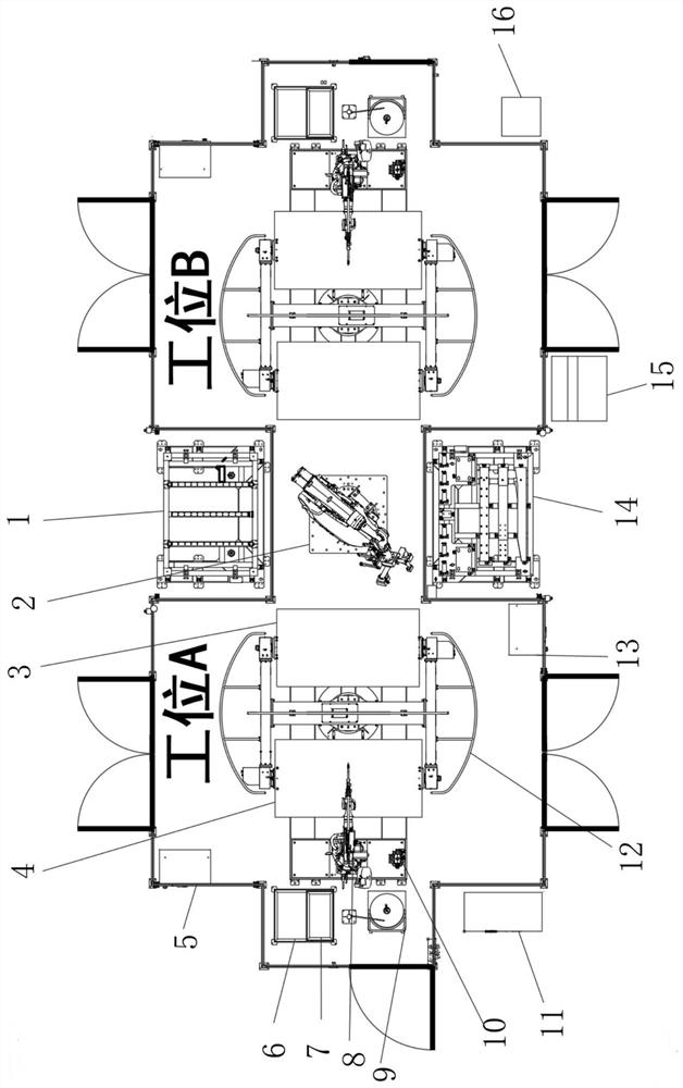
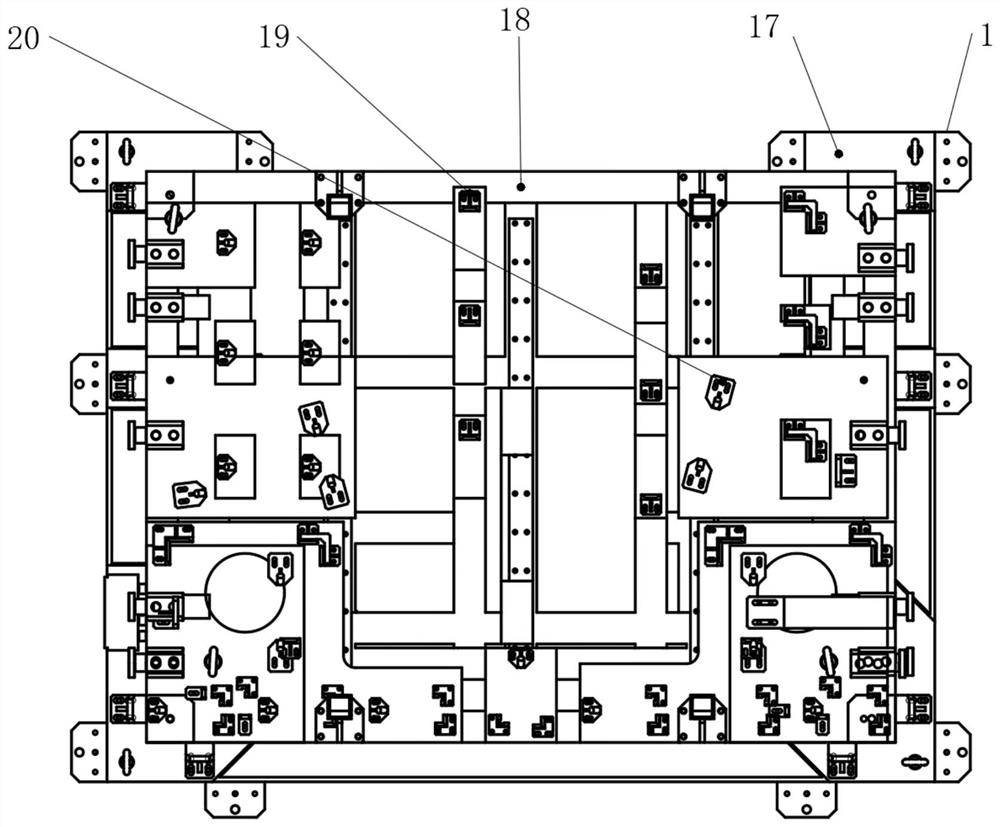
[0041] A steel box bridge engineering automatic welding fixture, such as figure 1 with 2 As shown, including the lower material level 1, the lower end position of the lower material level 1 is provided with an assembly robot 2, and the lower end position of the assembly robot 2 is provided with an upper material level 14, and one end of the assembly robot 2 is contacted and connected with a first welding fixture 3, The side end position of the first welding fixture 3 is fixedly connected with the second welding fixture 4 through the three-axis rotary positioner 12, and the side end position of the second welding fixture 4 is provided with a wire feeder 8, and the top of the wire feeder 8 There is a welding robot control cabinet 5 at the position, a welding machine 6 is connected to the side end of the wire feeder 8, a water tank 7 is provided at the lower end of the welding machine 6, and a wire feeding bucket 9 is connected to the rear end of the wire feeder 8. , the lower e...

Embodiment 2

[0051] On the basis of Example 1, such as Figure 10 As shown, the inner end of the three-axis rotary positioner 12 also includes a second light shielding assembly 34, and the second light shielding assembly 34 is fixedly connected to the top position of the first light shielding assembly 24 at the inner end of the three-axis rotary positioner 12.

[0052] When this embodiment is in use, by installing the second shading assembly 34 at the inner end of the three-axis rotary positioner 12, the second shading assembly 34 is arranged at the top position of the first shading assembly 24 at the inner end of the three-axis rotary positioner 12, They are fixed to each other to help perform efficient shading treatment, realize symmetrical shading operations at both ends, facilitate use, and perform external protection functions.

[0053] Working principle: When work is required, the user performs feeding work through the loading position 14, and assembles and connects the inner end thr...


PUM


Abstract

The invention discloses an automatic welding clamp for steel box bridge engineering, comprising a discharging position. An assembling robot is arranged at the lower end of the discharging position; a feeding position is arranged at the lower end of the assembling robot; one end of the assembling robot is in contact connection with a first welding clamp; a second welding clamp is fixedly connected to the side end position of the first welding clamp through a three-axis rotation positioner; a wire feeder is arranged at the side end position of the second welding clamp; a welding robot control cabinet is arranged at the top position of the wire feeder; a welding machine is connected to the side end position of the wire feeder; a water tank is arranged at the lower end of the welding machine; a wire feeding barrel is connected to the rear end of the wire feeder; and a gun cleaning station is connected to the lower end of the wire feeder. According to the automatic welding clamp for the steel box bridge engineering guardrail stand column, through the arrangement of the three-axis rotation positioner, the purpose of inner end displacement transmission connection is achieved.

Description

technical field [0001] The invention relates to the technical field of steel box bridge engineering equipment, in particular to an automatic welding fixture for steel box bridge engineering. Background technique [0002] As a world-class difficult project integrating "bridges, islands, tunnels, and underwater intercommunication", the Shenzhong Channel has a total length of about 24 kilometers, of which the bridge project is about 17 kilometers long. The design speed is 100 km / h, and its scale and technical difficulty are unprecedented. [0003] With the continuous development of automation technology, automatic welding technology has become more and more mature, and it has become more and more widely used in aspects such as assembly and welding, and has begun to be widely used in various fields of national economic production. Especially the manufacturing industries such as automobiles and steel box bridges are more prominent. The application of automatic welding not only h...

Claims


Application Information

Patent Timeline
IPC IPC(8): B23K37/04B23K37/047
CPCB23K37/0443B23K37/047
Inventor 吴茂传徐洪飞吴佰胜全先江杨曙光吕本飞咸云飞董招生董奇李建华
Owner 江苏杰瑞信息科技有限公司
Learn More