Multiscreen Display Device
A multi-screen display and screen technology, which is applied in the direction of using projection device image reproducer, static indicator, cathode ray tube indicator, etc., can solve the problem of unable to control the light source in brightness mode
- Summary
- Abstract
- Description
- Claims
- Application Information
AI Technical Summary
Problems solved by technology
Method used
Image
Examples
Embodiment approach 1
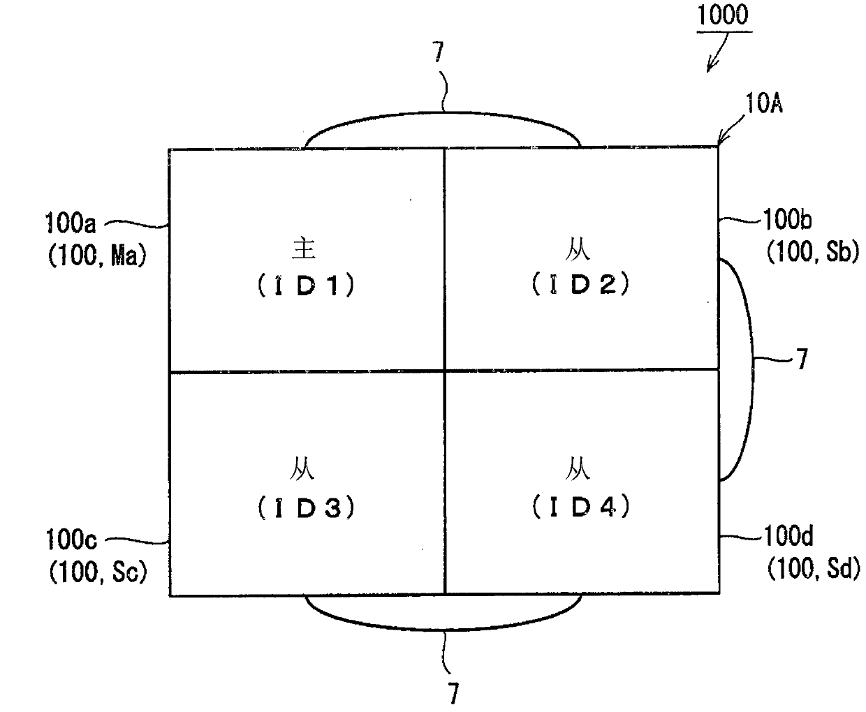
[0031] figure 1 It is a diagram showing the configuration of the multiscreen display device 1000 according to Embodiment 1 of the present invention. The multi-screen display device 1000 is composed of a plurality of projection-type video display devices capable of projecting video light constituting a video onto a screen (screen), and details thereof will be described later. In addition, the multi-screen display device 1000 is a device that displays video on a multi-screen composed of screens of a plurality of projection-type video display devices that communicate with each other. Hereinafter, the multi-screen display device 1000 will be specifically described.
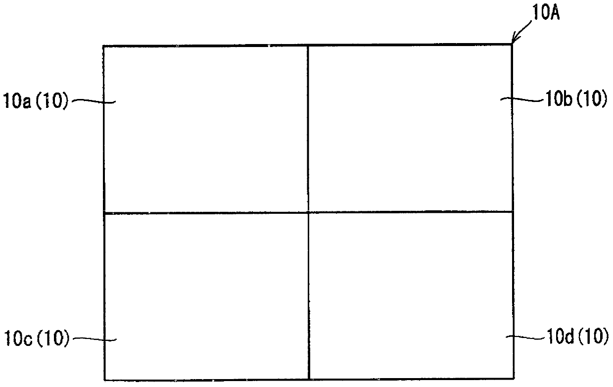
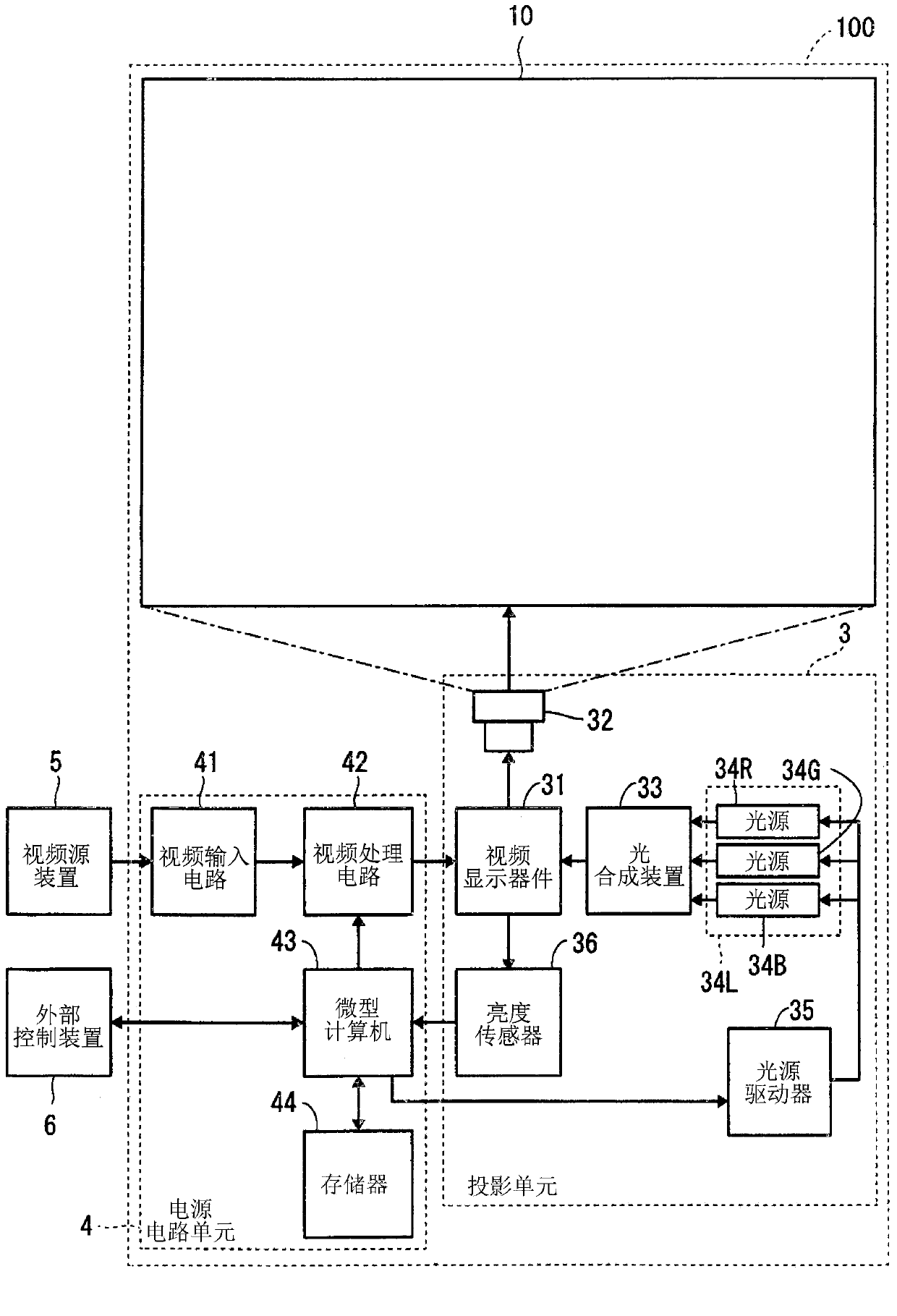
[0032] Such as figure 1 As shown, the multi-screen display device 1000 includes projection video display devices 100a, 100b, 100c, and 100d. Each projection type video display apparatus 100a, 100b, 100c, and 100d has the same structure, and details will be described later. Hereinafter, each of the projection-type ...
Embodiment approach 2
[0198] In Embodiment 1, processing for suppressing brightness variation among a plurality of projection type video display apparatuses 100 in the same brightness mode has been described. Here, the chromaticity value (chromaticity characteristic) of the LED corresponding to the control current value differs for each LED due to manufacturing variation or the like. Furthermore, in Embodiment 1, the control current value is calculated without taking chromaticity into consideration. Therefore, in the multi-screen display device 1000 according to Embodiment 1, the chromaticity may vary slightly.
[0199] On the other hand, in the multi-screen display device of the present embodiment, processing is performed to suppress not only variations in luminance but also variations in chromaticity. In addition, the multi-screen display device of this embodiment is figure 1 The multi-screen display device 1000. The following description will focus on processing different from that in Embodim...
Embodiment approach 3
[0302] In Embodiments 1 and 2, a method for reducing variations in luminance and chromaticity in the multiscreen display device 1000 was described.
[0303] In this embodiment, a description will be given of processing for solving problems that occur when the user using the multi-screen display device 1000 changes any one of the brightness modes of the projection-type video display devices 100 constituting the multi-screen display device 1000 . bad situation. This defect is such a defect that most of the luminance of the multi-screen display device 1000 changes. When this inconvenience occurs, the user will feel uncomfortable.
[0304] First, as a comparative example, a process (operation) that may cause discomfort to the user will be described.
[0305] As a premise, such as Figure 10 As shown, it is assumed that the multi-screen display device 1000 and figure 1 Similarly, it is composed of four projection type video display devices 100 . In addition, each projection ty...
PUM
 Abstract
Description
Claims
Application Information
 - R&D
- Intellectual Property
- Life Sciences
- Materials
- Tech Scout
- Unparalleled Data Quality
- Higher Quality Content
- 60% Fewer Hallucinations
Browse by: Latest US Patents, China's latest patents, Technical Efficacy Thesaurus, Application Domain, Technology Topic, Popular Technical Reports.
© 2025 PatSnap. All rights reserved.Legal|Privacy policy|Modern Slavery Act Transparency Statement|Sitemap|About US| Contact US: help@patsnap.com


