Air-conditioning system for a vehicle

A technology for air-conditioning systems and vehicles, which is applied to vehicle components, air handling equipment, heating/cooling equipment, etc., and can solve problems such as large installation space

Inactive Publication Date: 2015-06-03
MAHLE BEHR FRANCE ROUFFACH
View PDF11 Cites 3 Cited by
  • Summary
  • Abstract
  • Description
  • Claims
  • Application Information

AI Technical Summary

Problems solved by technology

However, the integration of such non-return valv

Method used


Image

  • Air-conditioning system for a vehicle
  • Air-conditioning system for a vehicle
  • Air-conditioning system for a vehicle

Examples


Embodiment Construction

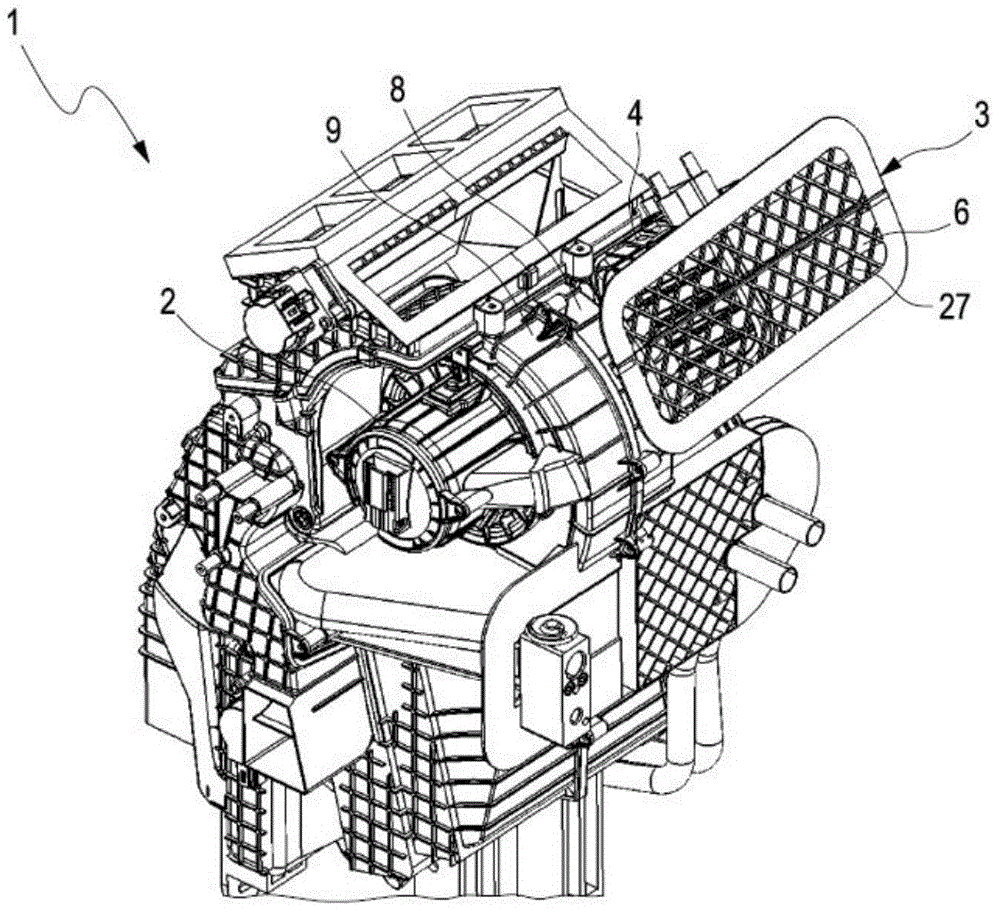
[0032] refer to figure 1 , in addition to having a number of other conventional components, the air conditioning system 1 can have at least one blower 2 for driving the air. Furthermore, the air conditioning system 1 comprises a control device 3 by means of which a changeover between circulating air operation and fresh air operation can be effected.

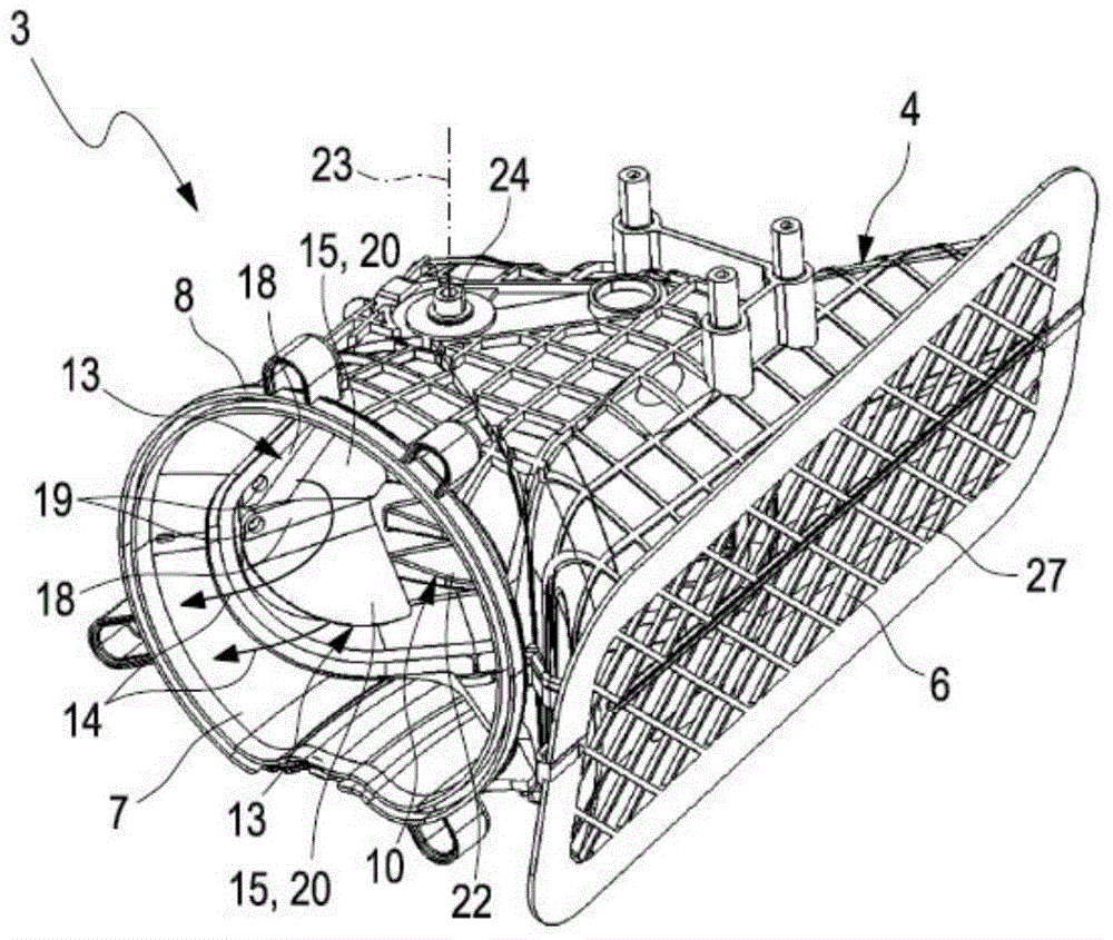
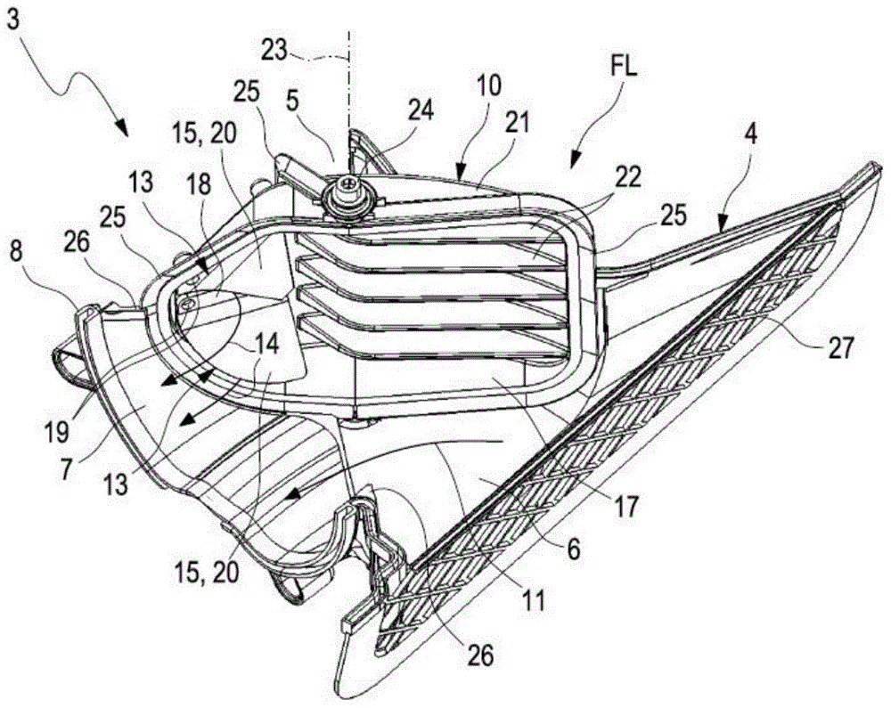
[0033] Refer to attached Figure 2-4 , the control device 3 can be equipped with a control housing 4 with which the control device 3 can form a preassembled unit which can be installed in the remaining air conditioning system 1 in a preassembled state. In any case, the control device 3 comprises a recirculating air inlet 5 (can be seen in image 3 , 4 ), fresh air inlet 6 (can be found in figure 1 , 4 ) and air outlet 7 (can be seen in Figure 2-4 ). The recirculation air inlet 5 is used to introduce recirculation air from the interior of the vehicle (not shown here) which is to be air-conditioned by the air conditioning s...


PUM


Abstract

An air-conditioning system for air-conditioning an interior of a vehicle may include a fan for driving air. The system may include a control device that may include a circulating air inlet for drawing in circulating air from the interior, a fresh air inlet for drawing in fresh air from an environment of the vehicle, and an air outlet. The control device may include a control valve adjustable between a circulating position and a fresh air position. The control valve may include at least one non-return check valve. The non-return check valve may permit a flow to pass through the control valve in one direction and block the flow in an opposite direction.

Description

technical field [0001] The invention relates to an air-conditioning system for air-conditioning the interior of a vehicle, in particular a passenger car, which has the features of the preamble of claim 1 . The invention also relates to a control device for the air conditioning system, and a control valve for the air conditioning system or the control device. Furthermore, the invention relates to the use of a control valve or a control device in said air conditioning system. Background technique [0002] A vehicle's air conditioning system typically includes a fan to move the air. The air used for air conditioning can be introduced into the fan from the environment outside the vehicle, this is the so-called fresh air. Likewise, air for air conditioning can also be brought in from the interior of the vehicle, this is called recirculated air. In order to be able to switch between the introduction of fresh air and the introduction of recirculated air, the air conditioning sys...

Claims


Application Information

Patent Timeline
IPC IPC(8): B60H1/00
CPCB60H1/00685B60H1/00849B60H1/24B60H1/00485
Inventor 亨利·克莱茵埃马纽埃尔·弗莱特
Owner MAHLE BEHR FRANCE ROUFFACH
Why Eureka
Try Eureka