
Winding mechanism

The technology of a winding mechanism and a driving mechanism is applied in the transportation of filamentous materials, thin material processing, transportation and packaging, etc., and can solve the problems of low degree of fit, damage to zipper floss, and narrow application range of the winding mechanism. To achieve a high degree of fit, to avoid the effect of strain

Active Publication Date: 2015-06-03
广东顺德三扬科技股份有限公司
View PDF5 Cites 15 Cited by
  • Summary
  • Abstract
  • Description
  • Claims
  • Application Information

AI Technical Summary

Problems solved by technology

Most of the existing winding machines do not have a correction mechanism, so that when the zipper floss is wound on the workpiece, the fit is low
Some winding machines with correction mechanism do not have adjustment function, so the scope of application of the winding mechanism is narrow
Moreover, the feed nozzle of the feeding mechanism of the existing winding machine does not have a stress structure, so that when the zipper dental floss is wound onto the workpiece through the feeding mechanism, rigid force is used to arrange the wire, which is prone to uneven winding or damage to the zipper dental floss.
[0003] Obviously, there are certain defects in the existing winding machine calibration and unloading mechanism, which cannot well meet the actual needs of users.

Method used


Image

  • Winding mechanism
  • Winding mechanism
  • Winding mechanism

Examples


Embodiment Construction

[0029] The specific embodiments of the present invention will be described below in conjunction with the accompanying drawings.

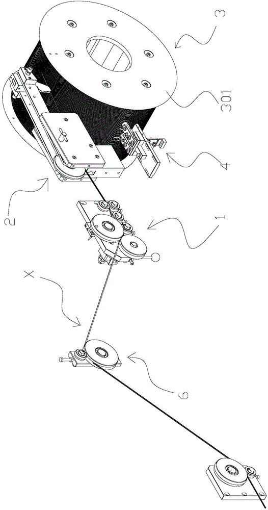
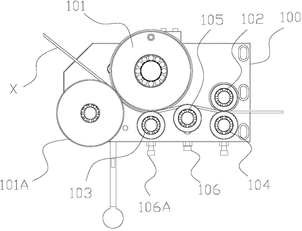
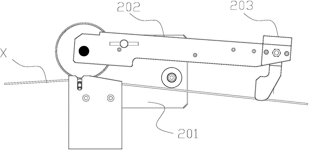
[0030] see figure 1 and figure 2 , the winding mechanism of the present invention includes a correction wheel set 1, a material guide mechanism 2, a drum 3 and a drum drive mechanism (not shown); the correction wheel set 1 includes a correction wheel set substrate 100, and is rotatably mounted on The first guide wheel 101, the second guide wheel 102, the third guide wheel 103, the fourth guide wheel 104 and the correction wheel 105 on the correction wheel group substrate 100, the first guide wheel 101 and the second guide wheel 102 are along the wire The conveying direction is arranged sequentially, the third guide wheel 103 is arranged on the lower side of the first guide wheel 101, the fourth guide wheel 104 is arranged on the lower side of the second guide wheel 102, and the orthopedic wheel 105 is arranged on the first guide wheel 102. Betwee...


PUM


Abstract

The invention belongs to the field of finished-floss manufacturing equipment, and particularly relates to a winding mechanism. The winding mechanism comprises a correction wheel set, a guiding mechanism, a roller and a roller driving mechanism; the correction wheel set comprises a correction wheel set base plate, a first guide wheel, a second guide wheel, a third guide wheel, a fourth guide wheel and a correction wheel, the first guide wheel, the second guide wheel, the third guide wheel, the fourth guide wheel and the correction wheel are rotatably mounted on the correction wheel set base plate, the first guide wheel and the second guide wheel are sequentially arranged along the conveying direction of a floss, the third guide wheel is arranged on the lower side of the first guide wheel, the fourth guide wheel is arranged on the lower side of the second guide wheel, and the correction wheel is arranged between the first guide wheel and the second guide wheel; the cooperation portion of the first guide wheel and the third guide wheel, the cooperation portion of the second guide wheel and the fourth guide wheel and the upper side of the correction wheel are floss conveying surfaces; the roller driving mechanism comprises a rotary driving mechanism driving the roller to rotate rotationally and a translational driving mechanism driving the roller to move periodically, axially and translationally. A zippered dental floss is subjected to correction by the correction wheel set to form a bend to be fittingly wound on the roller.

Description

technical field [0001] The invention belongs to the field of zipper dental floss storage equipment, in particular to a wire winding mechanism. Background technique [0002] The winding machine is a device that winds a thread-like object onto a specific workpiece, especially for the storage of zipper floss. Most of the existing winding machines do not have a correction mechanism, so that when the zipper floss is wound on the workpiece, the degree of fitting is low. Some winding machines with a correction mechanism do not have an adjustment function, which narrows the scope of application of the winding mechanism. Moreover, the feed nozzle of the feeding mechanism of the existing winding machine does not have a stress structure, so that when the zipper floss is wound onto the workpiece through the feeding mechanism, rigid force is used to arrange the wire, which is prone to uneven winding or damage to the zipper floss. . [0003] Obviously, there are certain defects in the ...

Claims


Application Information

Patent Timeline
IPC IPC(8): B65H54/30B65H57/14B65H59/10
Inventor 杨志舜
Owner 广东顺德三扬科技股份有限公司
Learn More